Thanks for assistance - it finally works!
With regards to series made by @chris - I’ve already seen it. It is fantastic but a bit too basic for me. This is mainly due to I am not an engineer and have different background (analytical to be precise). So now ahead of me is steep learning curve because I need to know why things are programmed in this, not other way how to set particular parameters to make the things work properly and receive accurate results. Hope You will not ban me for asking lots of questions Even the most basic things are very important
I would request you to elaborate on this. If you intend to know the theoretical basis for components, I would recommend you start with descriptions of the components. They usually provide links to papers that serve as their basis.
The idea of this forum is to help each other. You are welcome!
Also, I would recommend you start a new topic for this question please.
Fully agree that all such matters must be addressed in a separate post for better clarity.
With regards to the first item: I meant rather situation where i.e. I have a surface with decreasing elevation by 6 deg and how to design algorithm, what values for the components set to get accurate, true results. And this is for sure much broader knowledge that can be stored in a component description (and lack of engineering degree is not helpful ). The only thing that seems reasonable is to learn, test to the limit and then ask people on the forum to find out whether I have not made all wrong
I do have one more question with regards to the process principles. Why exactly there is a need to flip the surface? In case of simple geometries simulationg buildings it worked without it. Thy in this case does not? Where in default “sun” is located above the test surface to receive accurate results? Can anybody redirect me to anymethodology behind this operation?
Without having looked at your surface… it’s a matter of having the normals point in the correct direction. For closed polysurfaces, the normals will always point out and will therefore be correct. Depending on the way your surface was created, the normals can point up or down…
So - if I understood it correctly - the success of the analysis does not depend on the orientation of the surface (in this case horizontal) but direction of normals drawn from the centers of its cells? How in this case the simulation is being performed - are sun vectors resembling the real life angle they fall on the horizontal surface in each season (i.e. following the position the sun on a sunpath)? I’ve been looking for some explanation but was not able to find it,si if this matter was already explained - apologies for raising it again.
I’ve uploaded the surface for your review. How can I verify in which direction the normals are pointing? Is there a specific function for it?
@devang and @wim replies are correct. The direction of the surface is what Ladybug uses to generate the test points. The result that you get is for each test point (aka sensor). Each sensor has a location (x, y, z) and a direction (x, y, z).
Let’s talk about a simple surface and see what happens when you run a simple radiation analysis with Ladybug.
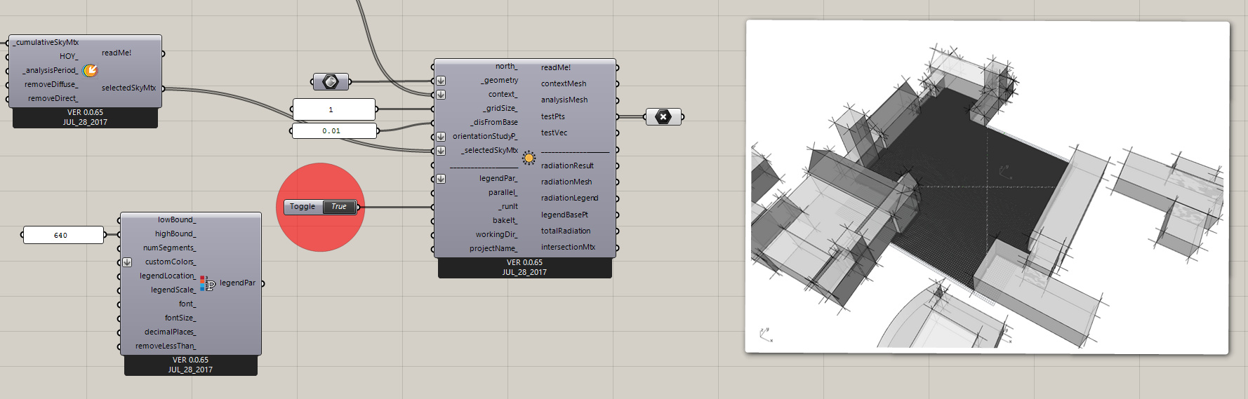
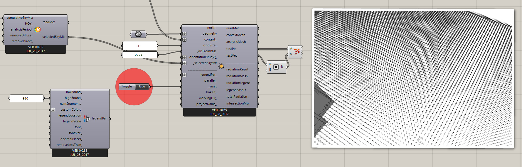
The component divides each surface based on the gridSize input, and uses the center point of each grid as the test point. Each center point represents the whole face.
It moves the test point away from the base surface by disFromBase. We need the test point to away from the surface not to intersect with the surface itself. The direction of the move is based on the normal direction of the point which is based on the normal direction of the center of each grid.
Here is when your example fails. If the surface normal is downwards then the direction of points will be downwards and also the points will be moved behind the test surface. That’s why you would get the value of 0.
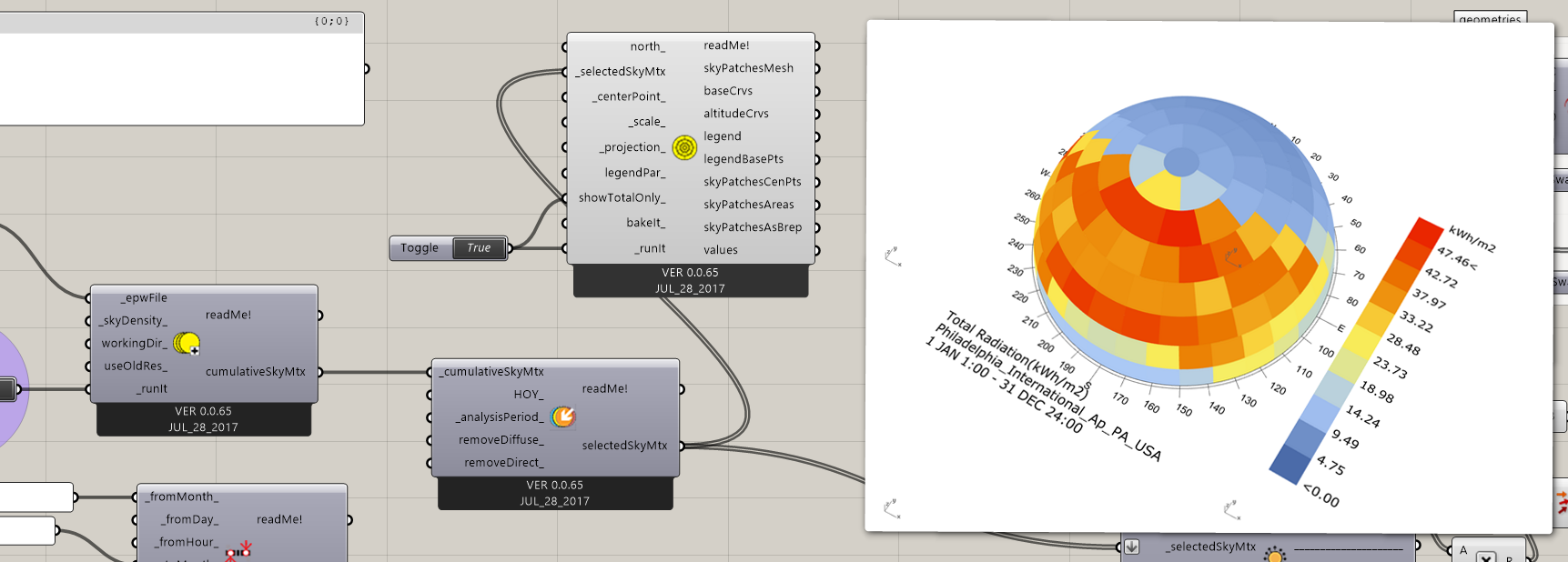
Finally, it calculate the amount of radiation that each test points receives from the sky (and not the sun). When you use the genCumulativeSkyMtx component ladybug uses Radiance’s gendaymtx to calculate the cumulative sky. Cumulative sky is not continuous and is divided into patches and the value for each patch is broken down to diffuse and direct values. Ladybug uses the center point of each sky patch for the calculation. You can change the density of the sky using the skyDensity input. The default is 0 which generate the Tregenza sky with 145 path.
For calculating the total value the value for each point is multiplied by the area of each grid. The component outputs both the raw value for each point and the total radiation.
In short, the calculation is for each test point and it will be different based on the direction of the surface/test point.
This component has two main limitations and should only be used for outdoor studies. The limitations are:
Component doesn’t calculate secondary reflections from the surfaces.
Component doesn’t accept transparent or translucent materials.
If those are required for your study then you should use Honeybee’s grid-based recipe which uses Radiance for ray-tracing and doesn’t have any of these limitations.

 ). The only thing that seems reasonable is to learn, test to the limit and then ask people on the forum to find out whether I have not made all wrong