As far as I know the Energyplus has the functions of day lighting and lighting controls. Can I ask why Honeybee choose to use Daysim to calculate these instead of using EP’s own functions?
And can I ask how to set an artificial lighting within Honeybee?
It mostly has to do with accuracy of the simulations. The raytracing engine within Radiance, which is what Daysim is derived from, has been thoroughly validated over the last three decades. Example 1 (1989): https://eetd.lbl.gov/sites/all/files/publications/lbid-1575.pdf, Example 2 (2018): https://escholarship.org/uc/item/24h966pp . You can find nearly three dozen such validation studies.
As far as using artificial lighting in Honeybee is concerned, it really depends on what your end goals are. If you are interested in just doing an energy simulation, then E+ will suffice. If you are interested in doing an accurate lighting simulation, then use the daylighting module in Honeybee with the IES components.
I think this video is still relevant:
You should be able to find a relevant Hydra example in the description.
I have a question on how daylight is calculated within Honeybee, forgive me if it sounds very silly. The primary question is on the sensor points.
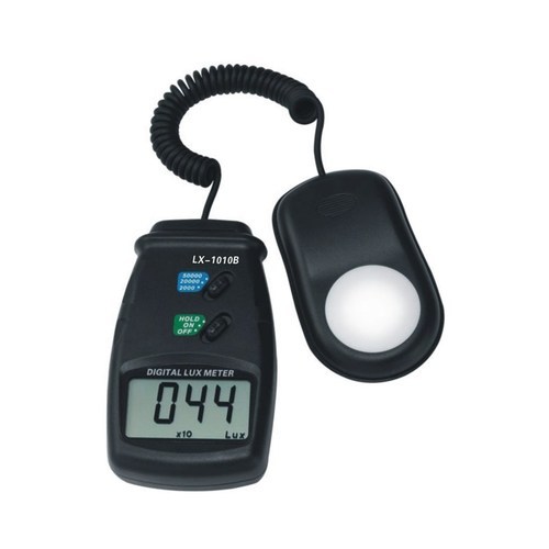
So, in the real world, we have digital lux meters right? such as the one shown in the fig. below
when we measure daylight on a work-plane, the hemispherical region of the sensor is exposed to the outside and thus the illuminance is measured. This also means that any light bouncing of the surface of the work-plane (for eg. a table) wont have much effect on the sensor as it is opaque below the sensor device and not in the “field of view” of the sensor.
But in LB/HB, the sensors are virtual points and hence any light bouncing of any surface can reach the point and the illuminance value is calculated as a sum of the direct + diffuse light falling on it? Is this right?
Sensors are defined with six real numbers, the first three correspond to the position of the sensor in real world coordinates and the next three correspond to the direction of the sensor in the form of x,y,z directional vector coordinates.
Usually the last three numbers are 0 0 1 (i.e. facing in the upward Z direction), thus mimicking an illuminance meter being used to measure horizontal illuminance.
In such a scenario, any radiation being reflected/emitted from the floor won’t have a direct impact on the illuminance value, unless that radiation hits the walls, glazing and ceiling and is then reflected on to the sensor.
Oh okay… Thanks Sarith for the elegant explanation… One last question.
If this is the case, when I am looking at a metric like (DGPs) where the vertical Illuminance of the points need to be measured, I will need to keep the vector of the sensor points as (-1 0 0) [as I have a south facing window] in order to measure the vertical Illuminance right?
How would I define this on my analysis grid? I can see that there is a parameter called points vector on my analysis grid component. But since its an output parameter, I don’t quite understand how that can be changed to fit my case.
Glare-based metrics like DGP usually involve the generation of HDR images with rpict. The vector direction in that case is assigned through the -vd flag, which Honeybee sets for you based on your Rhino viewport camera.
There is no analysis grid involved as instead of measuring illuminance on the workplane, you are measuring luminance on the pixels of an image.
Hi Sarith,
Thanks for your reply.
I understand that DGP metric works on the basis of image based simulations. But I was talking about DGPs (simplified DGP) where only the vertical illuminance is required and the metric can be derived using a formula for simplified DGP.
I read your post on the same here.
Wouldn’t it be important to define the vector of the analysis point? I saw a few example files where some users have done a simplified DGP calculation for their project where they have directly input the illuminance output of the three-phase simulation into a formula to derive the simplified DGP (where the analysis grid point vectors act like as mentioned in your earlier reply)
I have never been a big fan of the simplified DGP approach. Considering that it’s based on a singular study, I am not sure how much the accuracy aspect of it can be replicated in other simulations. In my opinion, it makes more sense to identify certain hours with high solar insolation and then conduct DGP analysis for those hours (rather than doing them for 8760 hours).
To answer your question, I’d apply whatever guidelines/methodology they describe in that paper.
Well, that approach (of using 3-Phase to calculate vertical illuminance ) is incorrect. There are numerous studies that point out the inadequacy of using the 3-Phase method to model direct solar contribution, the most definitive one being: https://www.sciencedirect.com/science/article/abs/pii/S0038092X17311118
I get that the 3-Phase approach is a lot simpler to setup and run, however it is almost certain that for all instances involving direct-insolation, the results will be far off from what the more accurate 5-Phase method will give you.