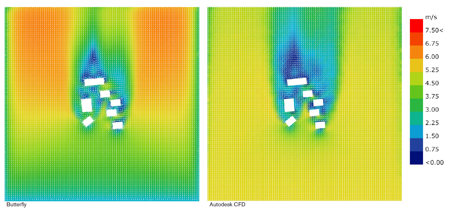
I am comparing results from Butterfly with those from Autodesk CFD. I created a simple urban wind model and ran both simulations with a base wind speed of 5 m/s. The buildings range in height from 10-20m. The results are displayed on a 3x3m grid, with a coloured mesh showing wind speed and white arrows showing direction.
The wind patterns seem quite similar, but there is an obvious difference in wind speed between the two simulations. I’ve inspected the meshes and they both are of good quality. Does anybody have any ideas about the difference in behaviour? It seems strange that the Butterfly results show such a low wind speed at the entrance of the tunnel (around 2 m/s), shouldn’t this be 5 m/s?
Any help would be much appreciated!! Let me know if you need more details
It’s really hard to say with the information provided. Mesh being ‘good quality’ is not enough for a comparison, it has to be identical in some way.
I would suggest to try and align all parameters between the model, mesh type, mesh size and refinement, wind tunnel dimensions, ground roughness, boundary conditions, incoming wind profile, turbulence model, and so on.
After that, you can run a comparison study and be a bit more certain of the results. If all or some of this is already aligned please let us know.
@nicholas and @TheodorosGalanos,
I remember those times that i tried to use AutodeskCFD and was so surprised and disappointed that to create/define the wind profile it needs to be done manually, literally, moving points in a profile scale on the software. Needless to say that this is an impossible mission. At that point i stopped my trials with this software.
It was a couple of years ago and suspect they didn’t implemented any more scientific solution to the issue. If they don’t, so there is nothing to compare here, sadly.
Maybe you know?
-A.
@AbrahamYezioro yes I’ve just experienced the same thing! After making this post I read that Butterfly automatically creates a logarithmic wind profile, so I’ve been trying to reproduce the same profile manually in Autodesk CFD.
As @TheodorosGalanos and @AbrahamYezioro noted Butterfly takes the input wind speed at a specific height (10 meters by default) and generates the wind profile. It makes sense to have a lower wind speed in a lower height. It seems in your study Autodesk CFD generates an inlet with a uniform wind speed.
Now I understand why the wind velocity is lower near the inlet for the Butterfly simulation! I checked the Autodesk CFD study and it does generates a uniform wind profile at the inlet.
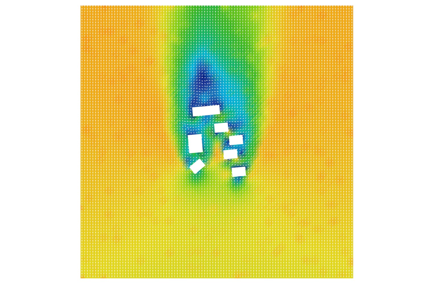
This is the best result I could get in Autodesk CFD after trying to match all the parameters including model, wind tunnel, boundary conditions, wind profile, ground roughness, turbulence model and mesh (the result doesn’t look great and I will ask for some more support on the Autodesk forum):
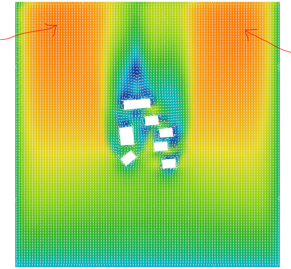
What I am most interested in is how in Butterfly, the wind speed increases a lot towards the exit of the wind tunnel (see image below). Does this behaviour seem reasonable to you for this scenario (the terrain is totally flat)? @TheodorosGalanos@AbrahamYezioro@mostapha
Thanks @nicholas for bringing this comparison. I just dumped the autodesk product a long ago for this kind of approach. Their hunger for making this popular but not reliable made me angry.
As for your question, “normally” it takes a long distance for the wind to recover to the undisturbed profile. So here you need to make a compromise between this and having a quicker result but still correct in your area of interest.
In your above i would reduce the distance from the inlet to the model and increase the distance to the outlet. You need shortest distance to crate the wind profile and larger distance to assure the wind will not return towards the model. Locating the model in the middle is not necessary.
BF wind tunnel has some defaults for this, but i don’t remember what they are.
-A.
Hi @nicholas Thanks for sharing all this. A uniform inlet will not do, certainly not for an urban case. If there is a way to script the logarithmic profile in Autodesk I would look for that (much like one can script it in StarCCM+).
Concerning the results, firstly we should note that the ground is not really flat. We are inputting a ground roughness to the model, most likely 1.0 which reflects a city area. This kind of creates a ground that is not considered flat even though there is no obstacle in the way.
As for the specific accelertion I think Abraham covered it nicely. You generally want to allow for a large extension on the leeward side (after the wind hits the area of interest), I would input a number between 10-15 in the leeward extension on BF windTunnelParameters component. This is because when we construct any CFD model, at least with our default settings in BF, we make an assumption. We assume that the pressure in the outlet is 0 (you can validate that by checking the boundary condition of the outlet patch in the p file, inside the 0 folder). To achieve that therefore, we allow a large extension that lets the freestream converge. A nicely converged study will always show that, a pressure that is near 0 close (and not only at) the outlet boundary.
Also you generally want to allow for a side extension, although the one you have now seems ok. You can try extending it a bit, maybe try 6 in the side extension input. I have a habit from the days of hand calculating grid expansion values to use the same number (6 in this case) for windward and side extensions but any number (usually equal or smaller than that) will do for your case. I think a best practice is somewhere around 3-4.
If your model gets too big from the choices above, you can try playing around with the blockMesh grading component. It can allow you to put a lot of refinement near your region and much less at the edges of your mesh. I typically have values like 200m even for individual cells near the end of my tunnel for example. My typical grading mesh settings is to set a blockMesh cell size of 1-2m at my region of interest and an expansion of 1.2 (max) from there to the edges (sides and outlet). For the inlet, I make sure the initial cell size is not too large. A value of 10m for the first cell would be good.
I finally get some time, I am planning to upload a number of BF definitions on Hydra, with the updated components, that show the logic of all this. Bare with me for a few days.
@TheodorosGalanos@AbrahamYezioro thanks for your replies! I’ve watched the webinar series from Theodoros, which was very helpful in setting up this study. So I already had an idea of how to set up the wind tunnel and generate a grading mesh.
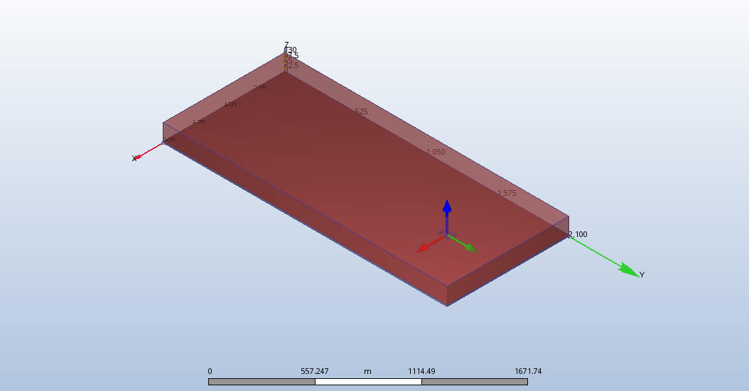
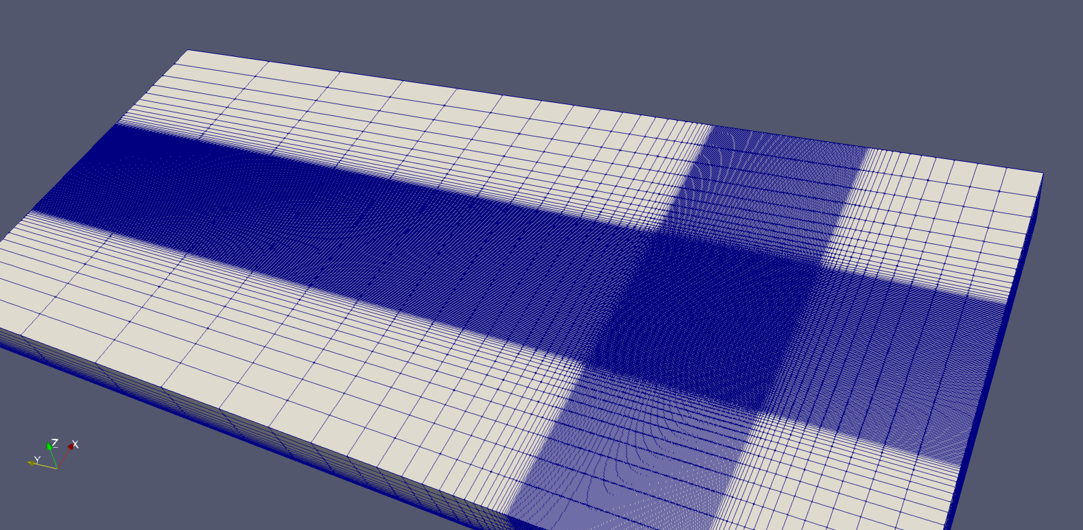
Sorry I didn’t explain before, but the results I posted only show my area of interest. The full wind tunnel looks like this in both Autodesk and Butterfly (screenshot from Autodesk CFD):
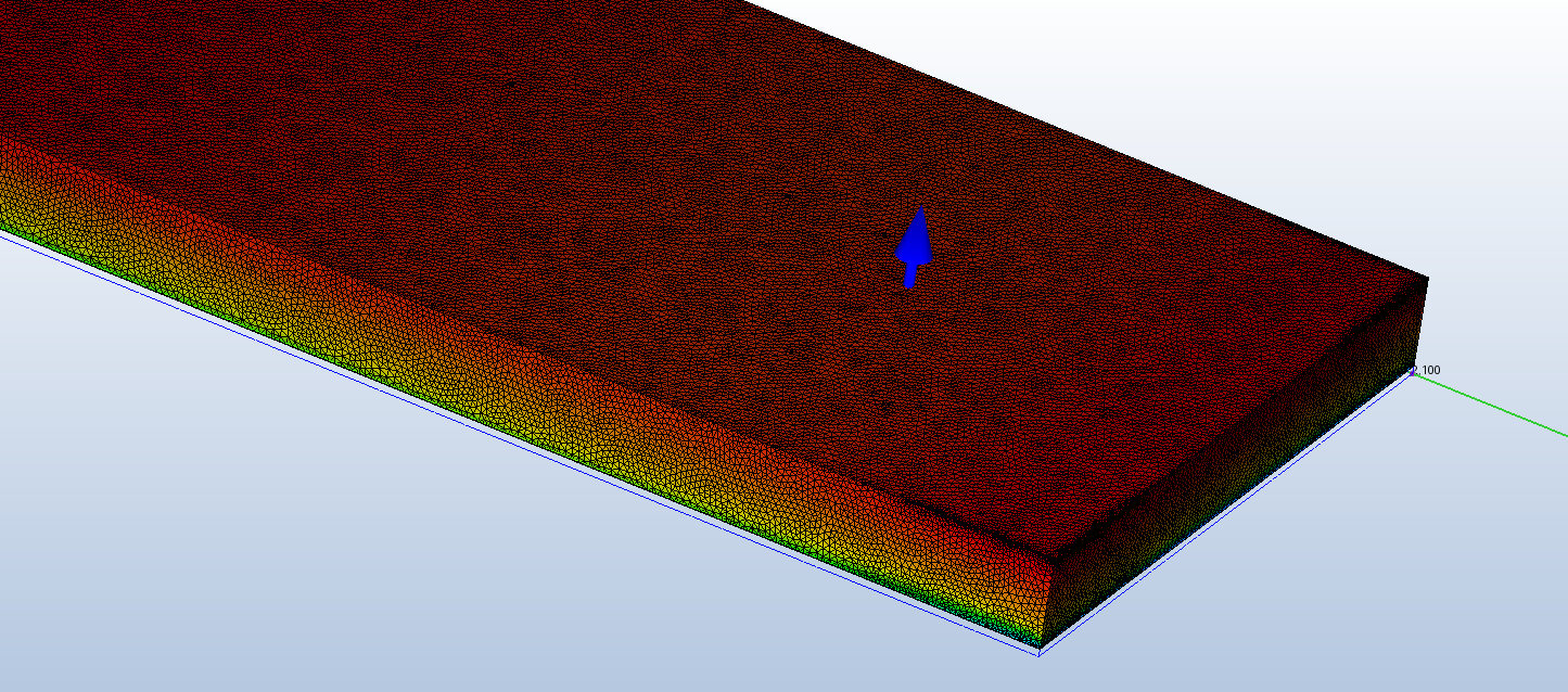
I couldn’t achieve the same mesh in Autodesk CFD, so I allowed the automatic generator to generate a mesh and then I applied an overall refinement so that the mesh around the buildings was approximately the same size as I set in Butterfly (ended up as a heavy mesh as the grading was very localised around the buildings). Here is a screenshot.
I also tried to match the wind profile (visible on the mesh above), by approximating a logarithmic distribution with the same ground roughness as in Butterfly. I had to use Excel to generate values for every 0.5m height in order to input the profile to Autodesk CFD (not pretty, but better than a uniform inlet).
Is there anything that I’m missing? I’m also posting on the Autodesk forum to see if they can identify something I’m doing wrong in Autodesk CFD.
Thanks again for your time. It’s very valuable to have your insight!