Fan electricity for ideal air loads

How to output fan electricity, additionally to cooling, heating etc, in simulation with ideal air loads?

I understand the ideal air loads system takes into account the ventilation rates set in the “Set Energy Plus Zone Loasd” component, but I can’t see how the energy to provide that ventilation can be shown in the outputs.

@EmanueleL

I am speculating here, but I think the fan electricity for ideal air loads doesn’t exist since the system doesn’t actually model any equipment. It’s just calculating the heat and mass transfers associated with various zone setpoints, and limit supply air temperatures.

As I understand it, the ventilation rate specified by the DesignSpecification:OutdoorAir is used to calculate the sensible/latent impact on zone conditions, which is probably done with something like this equation:

Qz = vm * Cp * (Tz - Toa)

where:
Qz = Zone sensible load
vm = ventilation mass flow rate
Cp = Specific heat capacity 
(Tz - Toa) = Temperature difference between zone and outdoor air.

So if the additional sensible heat from ventilation is greater or less then the load required to hit zone cooling or heating setpoint, respectively, the system calculates the increase in supply air flow rates required to hit the setpoints given supply air limit temperatures, again by solving the mass heat balance. The ideal air loads system then models the air mixing between supply and outdoor air, and so on, as documented in the Engineering Reference here.

So I don’t think the electricity used to drive the ventilation rate is used, or known at any point. Similar to how the system calculates heating and cooling energy based on similar mass and flow balances, and not by modeling a terminal with coils and fans.

That being said, I could be wrong. You can confirm this by checking the RDD outputs from the OpenStudio component to see if there’s any metric identifying fan ventilation energy, and plugging that in as a requested EnergyPlus output metric to see if it’s providing any values.

S

2 Likes

Hi @SaeranVasanthakumar, many thanks for your detailed reply.
I had a look at the available outputs for Internal Air Loads in the RDD file as you have suggested and you are right, Fan Electric is not available as output.

However I have found in the outputs the Outdoor Air Inlet Flow rate, which seems not the same flow rate that the standard “Honeybee_Read EP HVAC Result” gives. Do you think is possible to obtain a theorethical fan energy output postprocessing the hourly Outdoor Air Flow rates result?

I’ve done a quick test, but I’m not sure the assumptions are correct. Would the total fan power be:
Internal Supply fan + Outdoor Supply fan*2 (this times two to mimic an extract fan?)

See attached screenshot and script of the test. The model has two zones, both with Ideal Air Loads assigned, but one has heating and cooling setpoints set in a way that heating and cooling are never triggered. As you can see, interestingly there is still a minimum ventilation flow rate to meet the ventilation criteria set for the zone, which means that postprocessing this output would give the fan electricity also for “virtually unconditioned” zones using Ideal Air Loads. Do you think this assumption is correct?

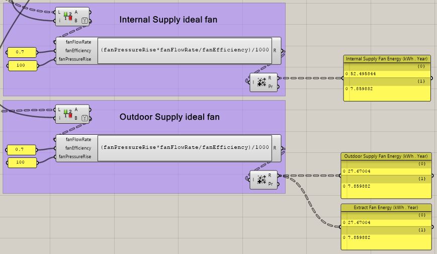
Fan for Ideal Air Load system.gh (570.8 KB)

@EmanueleL

I don’t know the answer to this question, but I’d also be interested in finding out if this is possible. I recommend posting your question to the Unmet Hours forum where you’ll have better odds of someone being able to verify your assumptions (although it may take a couple of weeks for someone to respond).

One thought regarding your fan energy equation:
image
If that is the mass fan flow rate I believe you need to divide by air density to get fan energy. If that’s the volumetric fan flow rate, that equation seems fine.

S

Hi @SaeranVasanthakumar,
I had a look at this more in depth and I found an easier way to work out the fan power. The method uses Specific Fan Power values (W/(m3/s)) and multiplies these for the airflow rate. The SFP of the system can be defined using the default values in the EN 16798-3 standard (see tables below).

Regarding the airflow in input, I believe with Ideal Air Loads the most appropriate input would be the Outdoor Inlet Flow rate, for a theoretical balanced system that only handles outdoor air supply and zone extract.
So shouldn’t be as I previously thought:
Internal Supply fan + Outdoor Supply fan*2
otherwise this would give the power of three systems running in parallel for AC supply, Outdoor Air and Extract.


GH definition attached
Fan for Ideal Air Load system_v2.gh (652.8 KB)

Regarding the airflow in input, I believe with Ideal Air Loads the most appropriate input would be the Outdoor Inlet Flow rate, for a theoretical balanced system that only handles outdoor air supply and zone extract.
So shouldn’t be as I previously thought:
Internal Supply fan + Outdoor Supply fan*2
otherwise this would give the power of three systems running in parallel for AC supply, Outdoor Air

@EmanueleL

Very interesting, that makes sense to me.

I feel like I’m missing something obvious here, but can you explain why you take the average of the Supply and Extract fans (multiply by 0.5), and not the sum?

S

@SaeranVasanthakumar
Sorry, you’re right, I misread the units in the formula


Should be the sum not the average, also for systems with a central unit e.g. a MHRV unit
…that is if you are using the EN standard values to calculate… If you use the Passivhaus standard value, that should be already the specific fan power of the entire system

Yeap, assuming QvSUP = QvETA, that’s right.

Thanks for sharing!

S