@SaeranVasanthakumar 's points are good but I will also add that engineers typically use a different method to size HVAC systems that does not involve an annual simulation like what you have run here. Because you are really only interested in the worst-case condition when you size an HVAC system, engineers will typically run the energy model through a detailed “design day” simulation or a day that mimics the wort-case conditions (using the data within the .ddy files). At the start of every EnergyPlus/Openstudio simulation with Honeybee, this design day calculation will be run to automatically size any HVAC equipment in the model. You can extract the result of this calculation using the “Honeybee_Read HVAC Sizing” component as you see in this example:
http://hydrashare.github.io/hydra/viewer?owner=chriswmackey&fork=hydra_2&id=Quantify_HVAC_Sizing_Impact_of_Shade
If you have a real HVAC in the model (not ideal air), this component will also tell you the actual size of the equipment, like the length of a chilled beam needed to meet the set point or the airflow that a fan coil unit must accommodate to meet the set point.
As for visualizations of the peak loads over the course of the design day, you can get this info out of the Honeybee simulation and it is helpful for understanding what is driving the resulting size of your HVAC. I have just pushed an example file that allows you to create these types of visualizations with Honeybee (and excel to make the nice-looking chart):
http://hydrashare.github.io/hydra/viewer?owner=chriswmackey&fork=hydra_2&id=Visualize_Peak_Loads_for_HVAC_Sizing&slide=1&scale=1&offset=0,0
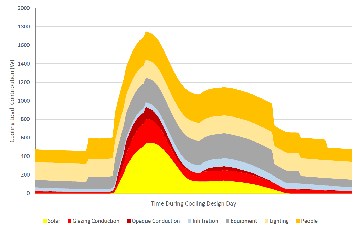
There are a couple of important things to keep in mind when you use these visualizations:
-
As you see in the example file, when you build these visualizations, you want to make sure that you are only looking at the sensible load in the space (not the latent) since it is ultimately the sensible heat that determines the size of the equipment needed to cool the space to the temperature set point. This isn’t to say that latent heat is not important but it primarily plays a role in sizing the ventilation system and not the equipment that heats/cools the space.
-
The peak sum of the instantaneous loads in your chart visualization is typically going to be more than the result that you get from the “Honeybee_Read HVAC Sizing” component. The result from the “Honeybee_Read HVAC Sizing” component is actually what is being used to size the HVAC both in EnergyPlus and for an engineer. This difference is because the chart visualization is only showing you the heat instantly flowing into the space and does not account for the thermal mass of the space or the time lag between when heat enters the zone and eventually gets translated to sensible heat in the air. Once you account for this, your peak typically becomes a bit smaller.
I hope that helps!