One Legend for Multiple Zones in Daylighting Simulation

Hello

I am wondering how I can create only one legend, rather than multiple, for daylighting simulation in case I have multiple zones? basically, HB creates one legend per space and I want it to eliminate those and create one big legend for my whole floor plan. Please see the attached files.

Thanks for your help

Ladan


CCC_Honeybee_Gridbased_22_11_16.gh (590 KB)

join the mesh and flatten the results: http://www.grasshopper3d.com/group/ladybug/forum/topics/remove-lege…

Thanks Mostapha, I created them like this (see the file attached) but it didn’t work. I used “Mesh Join” and “Flatten Tree”. Is there another command that I should use?

thanks

Ladan


Hi Ladan,

As Mostapha said, You need to join the meshes (not flatten) and flatten the illuminance values in order to have a common legend. I attached an example file. It is the same I sent you earlier. I have prepared a common legend in the file for your reference.

Devang

Test2.gh (487 KB)

  1. You need to flatten the input before the MeshJoin and not after. If you do it correctly the output of MeshJoin should be a single joined mesh.

  2. Flatten the results of the analysis before connecting them to recolorMesh.

Basically what we are trying to do is to change the results of different surfaces to look like the results of the analysis with a single surface.

Thank you very much Mostapha and Devang, it worked! that’s perfect! I am attaching the file for others reference.

So many thanks to you!

Ladan


Cool!

Hi

I’m facing the same problem that Ladan. But I don’t know where to place the “Mesh_Join” and the “Flatten Tree” in my file (in attach).
My file is based on Mustapha’s file used in Australia seminar avaliable on https://ladybug-tools-academy.teachable.com/

I’ll be very gratefull if someone could help me.Honey-FLD-Apto_01.gh (534.0 KB)

I guess this should work.

Exemplo Apto Base Rhino_05.rar (196.5 KB) Thanks a lot Tejas!
the legend worked perfectly.

But now I’m facing another issue…

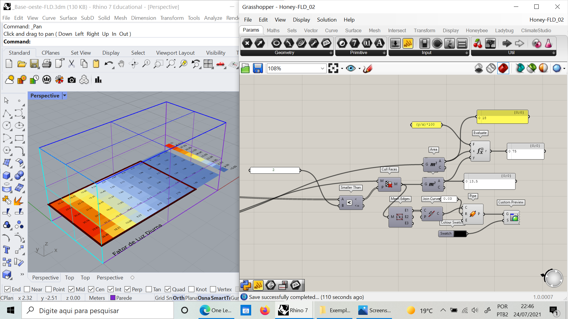
I’d like to show the area above DF 2% as in this single zone simulation (image below)

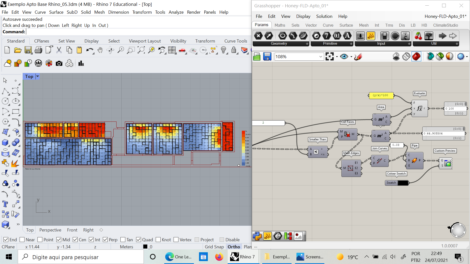
But when a do it in my multizone simulation (image below) it doesn’t work. The analisys plans appears all incorrectly subdivided.

Anyone can help me with this issue?

Im also sending my Rhino file in attach

Thanks!

Dear Ladybug fellows

I’ve found the solution. The analysis plans brep must be directly connected to test geometry to generate the simulation points.

Thanks for your help!!!