@TheodorosGalanos @AbrahamYezioro thanks for your replies! I’ve watched the webinar series from Theodoros, which was very helpful in setting up this study. So I already had an idea of how to set up the wind tunnel and generate a grading mesh.
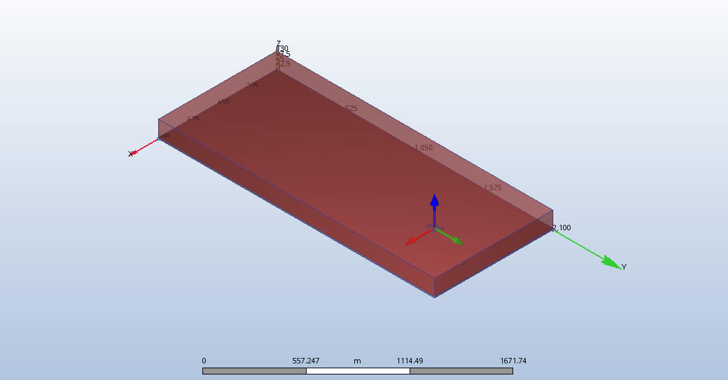
Sorry I didn’t explain before, but the results I posted only show my area of interest. The full wind tunnel looks like this in both Autodesk and Butterfly (screenshot from Autodesk CFD):
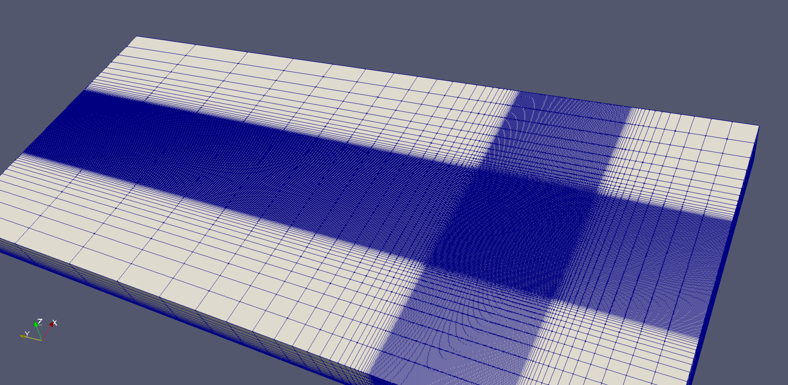
Also, here is an image of the grading mesh I used in Butterfly (shown in ParaView):
I couldn’t achieve the same mesh in Autodesk CFD, so I allowed the automatic generator to generate a mesh and then I applied an overall refinement so that the mesh around the buildings was approximately the same size as I set in Butterfly (ended up as a heavy mesh as the grading was very localised around the buildings). Here is a screenshot.
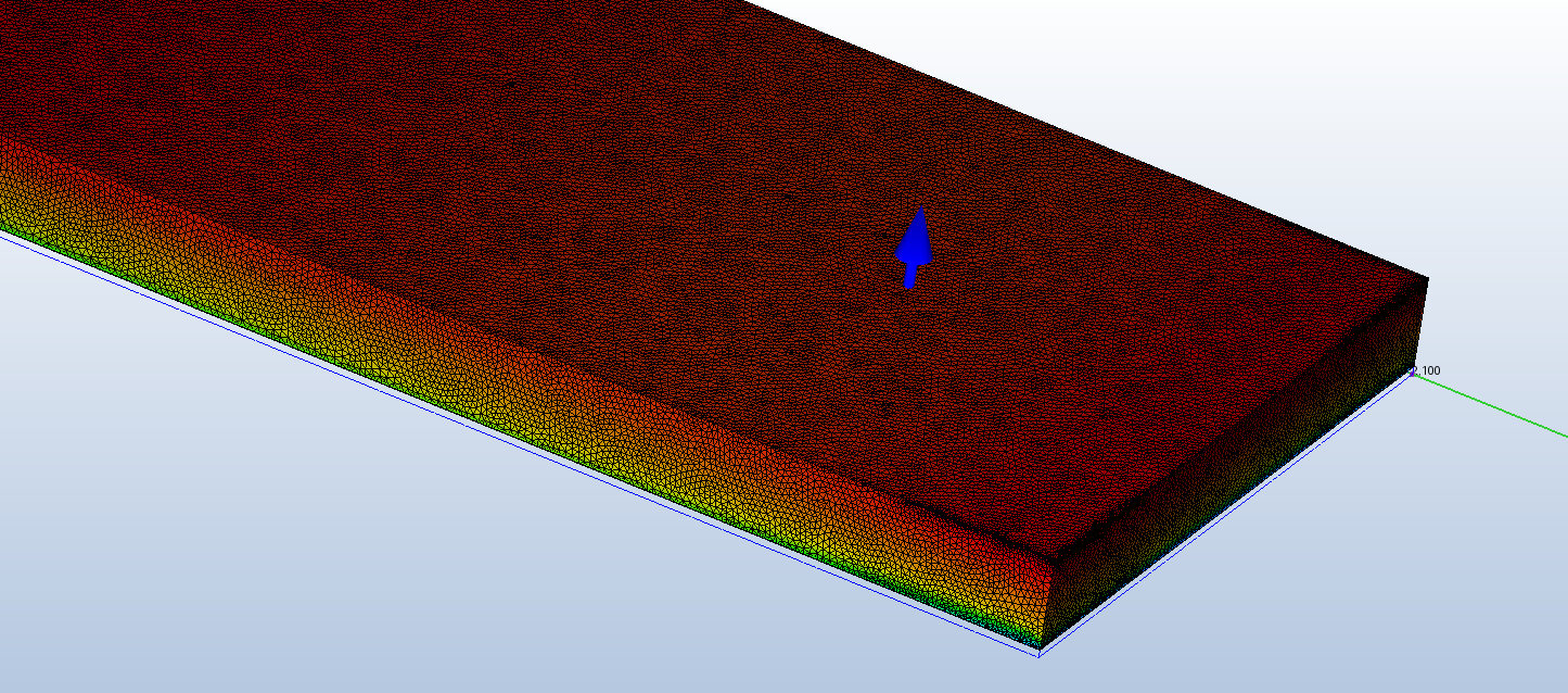
I also tried to match the wind profile (visible on the mesh above), by approximating a logarithmic distribution with the same ground roughness as in Butterfly. I had to use Excel to generate values for every 0.5m height in order to input the profile to Autodesk CFD (not pretty, but better than a uniform inlet).
Is there anything that I’m missing? I’m also posting on the Autodesk forum to see if they can identify something I’m doing wrong in Autodesk CFD.
Thanks again for your time. It’s very valuable to have your insight!