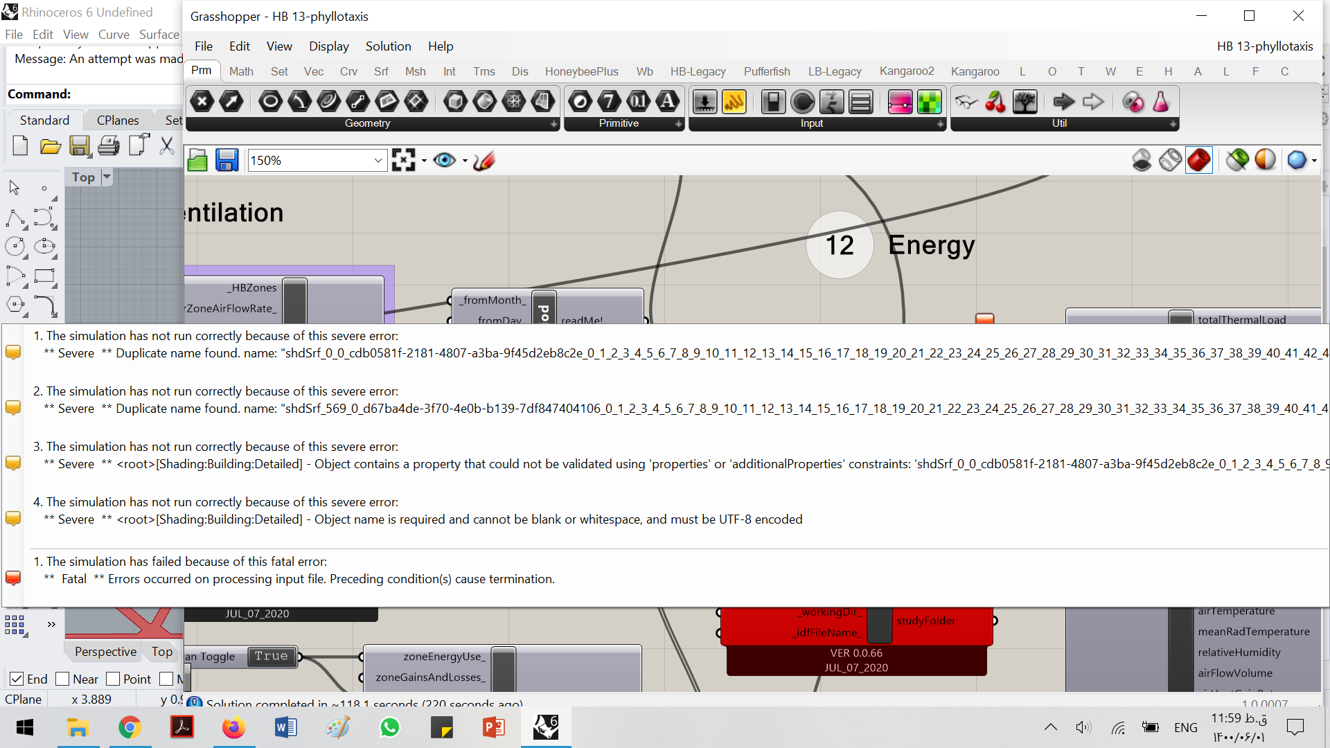
Hello. I have some errors such as duplicate name and the object name is required and the third error that I have no idea about it. Nowhere has a name for the shading.
I’m pretty sure this is happening because of my and Mostapha’s poorly written methods for dealing with non-planar geometry in Legacy. If you don’t want to clean up and planarize your geometry, I strongly recommend just using the LBT 1.2 plugin instead.
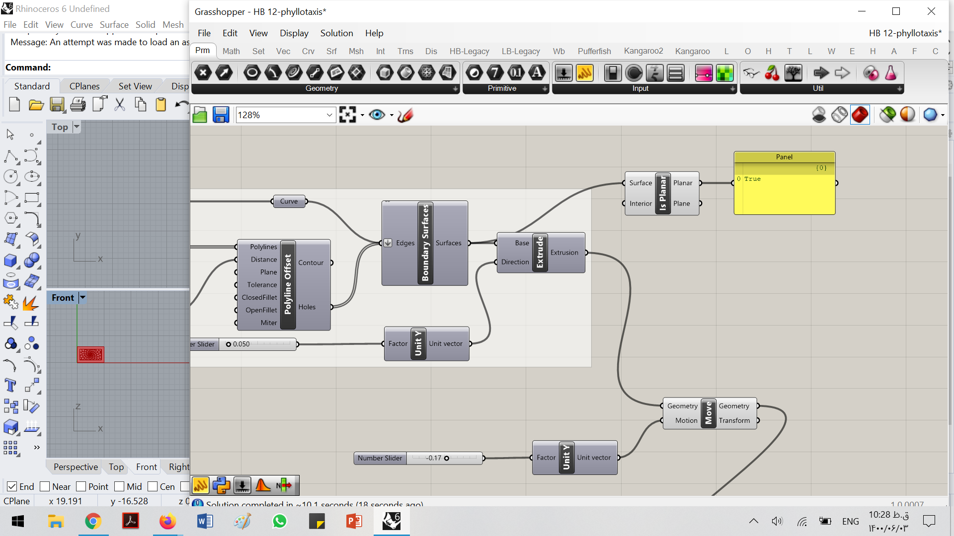
@chris, I am thankful for your response. I think it was my mistake that I didn’t know that shading should be planar geometry (like my last post), and I don’t have enough information about changing non-planar to planar geometry.
By the way, I think I have to change the algorithm of the shading because all components in the new version of HoneyBee have changed.
If I am not mistaken; out of the 550 surfaces the first and last are these faces of the object creating the issues. ( hole having planar surfaces and the legacy bugs are not friends at times )
If using the new release is a non-option:
If you break up these two faces (the front and back face of the geometry as depicted in the image) into the ‘individual frames’ of the geometry so there are no longer any ‘holes’ in the surfaces, that may well allow this to run using the legacy bugs but I am not 100% sure
@TrevorFedyna Thank you for your reply.
If I use list item and just use front, back, or both faces of geometry, it is like that I didn’t extrude it but the analysis didn’t work with the surface too. Of course, if I understand your explanation correctly.
Yes I tend to not articulate well, my apologies.
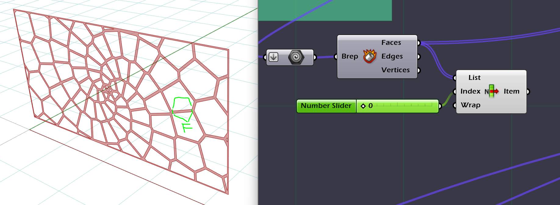
So the surface in the above image for instance: Contains ’ holes ', I believe that these ‘holes’ may be a part of the issue of why the geometry is not being accepted for the simulation.
So if you were to bake the surface above, you would be able to draw lines manually to ‘break up’ the surface into multiple so there would not be any one surface containing holes: I think that may be a solution but: like @chris said; it would better to use the new release if possible for you.
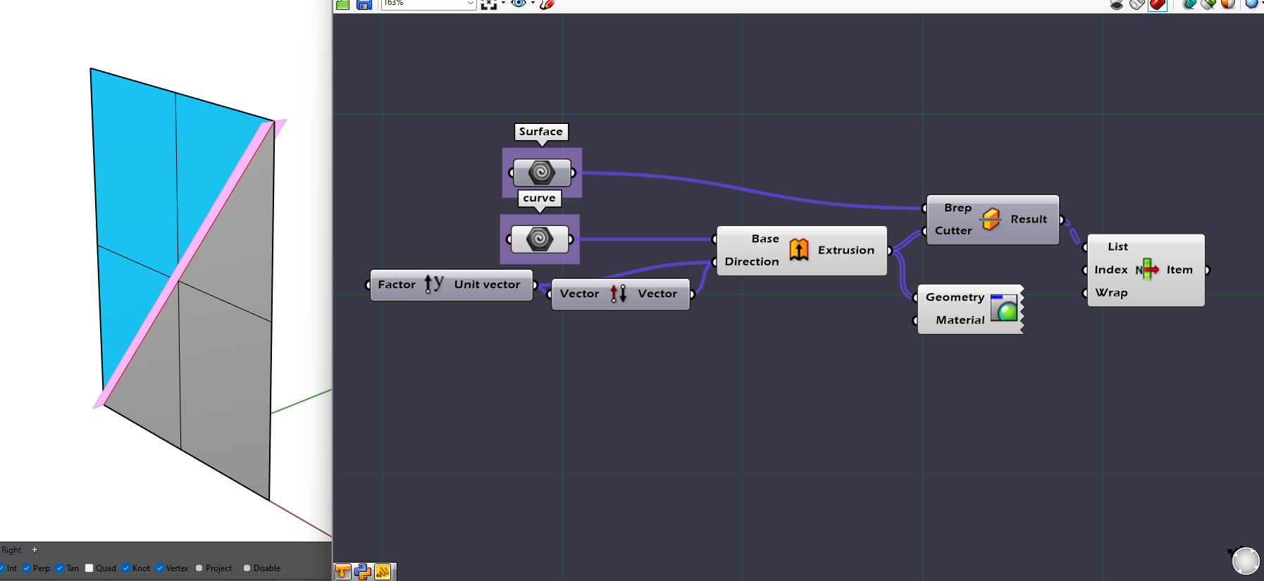
example:
with the grey rectangle as the surface to cut, a line was drawn and then extruded (pink Y axis diagonal ) and cut the grey surface in two ( see the blue triangle)
The list item is just being used to show one surface post brep split.
But yeah; I’m not 100% sure that will work but have a feeling that it may be a solution.
I am sure there is a more elegant way to break up that complex surface programmatically but this method may offer a simplified solution.
@TrevorFedyna Thank you very much for your complete explanation. I tried it but it didn’t run with just surface or extruded surface. On the other hand, I need it parametric for optimization. It has some problem with shading and I think I have to try the newer version as @chris said. Thank you for your help.