Ed - I saw a while ago your share post for the Psi-Value calculator. Many thanks for this! Very helpful indeed.
The post kind of reminded of a more general thermal bridging question/concern I have, which has to do with potential differences between 2D steady state heat transfer modelling software (such as LBNL’s THERM) and 3D steady state heat transfer ones (such as Physibel’s Trisco/Solido - although, I haven’t personally used them and I know they are quite expensive).
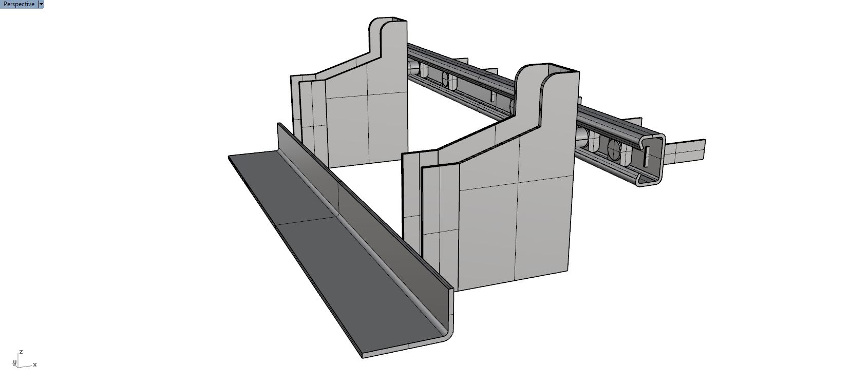
Couple of construction examples I have in mind are modelling of a thermal break between a cantilever steel balcony and a reinforced concrete slab (e.g. Schock’s Isokorb type KS, which is a very normal case in the UK residential sector), or a masonry support angle (e.g. image below - this one comes from Ancon if of interest).
In this example, both the plan section and the short vertical section vary across their respective axis. In reality heat transfer is a 3D phenomenon. Do you think that there’s a ‘correct’ 2D section that could capture a relatively accurate situation of such construction elements? Would you model a worst case one?
Yes I agree that there are currently very few good / inexpensive solutions for 3D Thermal Bridge tools - its probably the biggest missing piece of our toolkit at the moment in our office and if anyone knows any good ones I’d personally love to know more. I know several folks who are using Heat3 for this purpose as well as Trisco and Psi-Therm but they are all (in my experience) quite clunky to actually model in. If there was a solution which connected to Rhino that would be terrifically useful. The simulation math seems to be relatively straightforward and outlined quite clearly in ISO 10211.
And yes, there are some super expensive ones out there like NX Thermal and Comsol too but I haven’t ever gotten my hands on those.
There is an open source tool named ‘Elmer’ but I haven’t personally used it and not sure if it would work for this issue. It may be worth investigating if you are interested though.
To your other point about approximating 3D heat flow with multiple 2D ‘slices’ - while I don’t think anyone would tell you it was ‘correct’, I can certainly say that we’ve done it plenty of times as a better-than-nothing solution to these kind of things.
Within the tool we use the most for 2D simulation (Flixo) there is also some limited functionality for simulating ‘effective’ 3D bridging from small elements which is good for screws and the like. There is also a whole methodology within the ISO 6946 (used to be Annex D: Corrections for Mechanical Fasteners but in the new version I think its in Annex F now) which shows a simplified equation for calculating a U-Factor ‘supplement’ (added to the base U-Factor of the assembly) based on some input data about fastener material, spacing, size, etc…
@edpmay - Many thanks for the thorough reply and all the information. I would search more into all of them. I have recently started taking baby steps into thermal bridging modelling, and there’s a lot understand/learn. HB Therm seems as a very promising workflow to start even if it’s 2D.
Regarding 3D tools, two people I know in London who specialise in this have purchased Physibel’s Solido - definitely not an inexpensive solution, but they seem pretty happy with it. I think they model different construction parts in Rhino and then they export/import the .STL files.
I Just wanted to add more of an explanation for why there aren’t more 3D finite element interfaces and why the few that are around cost a lot of money and are clunky (which is not necessarily an accident or a mark of poor design).
As anyone who has used OpenFOAM and Butterfly on this forum cold tell you, 3D finite element modeling is difficult not necessarily because the underlying math of FE is difficult but because of one critical step in the process of using FE: meshing.
Meshing is an art in and of itself and, without a good mesh, you will not have an accurate FE model. Adding the third dimension quadruples the complexity of this meshing process and these meshing routines are what make 3D finite element interfaces very difficult to code.
In fact, if I had to say what the biggest contribution of THERM is to the practice of thermal bridging, it is the fact that the meshing is so seamless that you barely notice that it’s being calculated (unless it fails, of course )
All of this is to say that 3D finite element heat flow modeling requires a bit more than just a lot of money to buy software but also a deep understanding of how meshing works and what the meshing algorithms that you are using do. So it may be best to work your way towards 3D heat flow modeling by matering some 2D techniques and getting a feel for 3D meshing from Butterfly.
I’ll try to post back later with more a description about how to use 2D models to approximate 3D heat flow. There are 2 main methods that I use and using them both, I can usually arrive at pretty close approximations of 3D heat flow.
@chris - Thanks a lot for the explanation, tips and guidance - very much useful as always. In terms of the methods to approximate 3D heat flow via 2D models… I would be grateful!
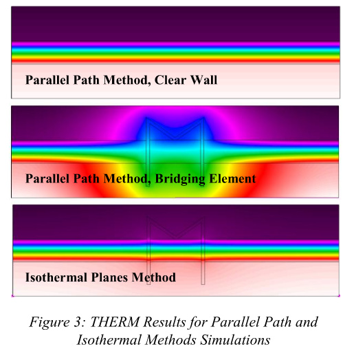
There are two methods that are commonly used to estimate 3D thermal bridging for elements that are discontinuous in the “z” axis of a 2D simulation:
The Parallel Planes Method (aka. Parallel Path)
You make two 2D THERM models: one that includes the thermal bridge and another that does not include it. You calculate the cross sectional area of the construction that is characterized by each THERM model. You then use this area to make an area-weighted average U-Value between the two THERM models. This method underestimates the impact of the thermal bridge.
The Isothermal Planes Method
For the thermal bridge element that is discontinuous in the Z-axis you calculate an area-weighted conductivity between the bridge and the insulation that is in place of it throughout the rest of the construction. You then build one THERM model and you assign a material with this area-weighted average conductivity to the thermal bridge element. This method overestimates the impact of the thermal bridge.
Either one of these methods can be pretty far from the true U-value but, if you average the results of these two simulations together, you typically get very close to the 3D thermal bridge U-value. As I mentioned previously, I would recommend mastering these methods before engaging with 3D thermal bridging software. This will at least give you a baseline that you can validate your first 3D thermal bridge simulations against.
I am working on some studies that involve the parallel planes method and isothermal planes method. You mentioned here. I have read Andrea Love’s paper on Assessing thermal bridges in commercial wall systems and I was looking to recreate this method, however the way she calculated the zones for her validation example was a bit confusing specifically on the area of influence. Then when you see the isothermal planes method THERM image it looks like there is no bridging happening. It seems like they are calculating the area of influence similar to a traditional stud wall condition but how would that be created in THERM via HB without the bridging effect occurring. In an example of a brick tie that has a known conductivity, I can calculate on paper the values and basic area of influence, but I am not sure how this would be created in a GH file.
I may be over thinking the issue, but if you have any thoughts or can elaborate, I would appreciate it. I am looking to understand and apply these methods in addition to using validated catalog information that is available.
 )
)