Chris,
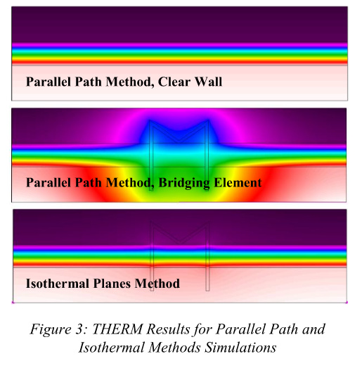
I am working on some studies that involve the parallel planes method and isothermal planes method. You mentioned here. I have read Andrea Love’s paper on Assessing thermal bridges in commercial wall systems and I was looking to recreate this method, however the way she calculated the zones for her validation example was a bit confusing specifically on the area of influence. Then when you see the isothermal planes method THERM image it looks like there is no bridging happening. It seems like they are calculating the area of influence similar to a traditional stud wall condition but how would that be created in THERM via HB without the bridging effect occurring. In an example of a brick tie that has a known conductivity, I can calculate on paper the values and basic area of influence, but I am not sure how this would be created in a GH file.
I may be over thinking the issue, but if you have any thoughts or can elaborate, I would appreciate it. I am looking to understand and apply these methods in addition to using validated catalog information that is available.
Thanks in advance.
https://ibpsa-usa.org/index.php/ibpusa/article/download/433/419