For an academic research, I need to calculate the U-value of thermal bridges in a diagrid structure construction with pretty complex geometry. I used HB + THERM to estimate the u-value of some sections in 2D; but at structural joints, 2D conversion seems to be oversimplified.
I would appreciate it if you could suggest a method or a free software to simulate and calculate U-value in 3D.
Unfortunately, there’s no freely-available software that I know of that will do 3D finite element heat flow similar to THERM (if there was, I would have built a connection out to it by now ). In my personal experience (and in the experience of many researchers), we have usually been able to get around this need for 3D by building several 2D models at different sections across the detail and then adding the heat flows of each section together. You can get these heat flows by multiplying each U-value by the “tributary area” that the section represents (I’m using an analogy to structural modeling here). Then, you divide the resulting summed heat flow by the total area of the tributary areas covered by the sections to get the heat flow through your full detail.
I’ll try to see if I can find some examples of research papers that have used this method and post them here.
I will also say that the only 3D Finite Element heat flow modeling software that I know of is RadTherm, which is proprietary and prohibitively expensive for pretty much anyone who does not have an academic institution willing to pay for it. Maybe that is able to address your situation but, if not, I imagine that the fist option of making multiple cross-sections will get you really close.
To add to Chris’s comment you may also want to try Kiva. It is still a new addition to EnergyPlus and I haven’t used it myself but might be the right software for your problem. It’s free and open-source and part of the EnergyPlus installation.
From the page:
Features
Two- and Three-dimensional heat transfer calculations
Flexible description of foundation structural and insulation elements (including thermal bridges)
Models slabs, crawlspaces, and basements
Validated against IEA BESTEST for ground-coupled slabs
Generates ground temperatures for use in whole-building energy simulation tools
Control over numerical and meshing inputs, though knowledge of numerical analysis is not required
Dear Mostapha,
Many thanks for introducing Kiva, but it seems to be usable for foundations with orthogonal geometry. See the parameters here. Only vertical and horizontal insulation is supported. (?)
You beat me to bringing up the orthogonal geometry limitation. From my understanding of KIVA, it only simulates orthogonal geometry because the methods for meshing orthogonal geometry are relatively straightforward. Good triangulated meshes that can be applied to non-orthogonal geometries are much harder to generate reliably.
Much like CFD, the accuracy of conductive finite element heat flow calculations is dependent on having a good mesh and it took a lot of effort to build THERM’s meshing engine in a way that accommodates all of the geometry that it does. Even considering this, it’s still common to get THERM’s meshing algorithm to fail when you model a detail that is too large or complex. Breaking your details down into smaller pieces is generally the recommended method for working in THERM, whether this is by separating the different elements of a window frame (sill, head, jamb) or breaking down a single detail into multiple cross-sections (as seems to be the case here).
And, much like the zoning of a full-building energy model, there is an art to how you break down your model into discrete sections.
@AryanShahabian , If you can share an image or file of the detail that you are trying to model, we can probably help you decide on the best way to slice it into sections. It helps to have an intuition about how heat will flow through the detail before you decide how to slice it up.
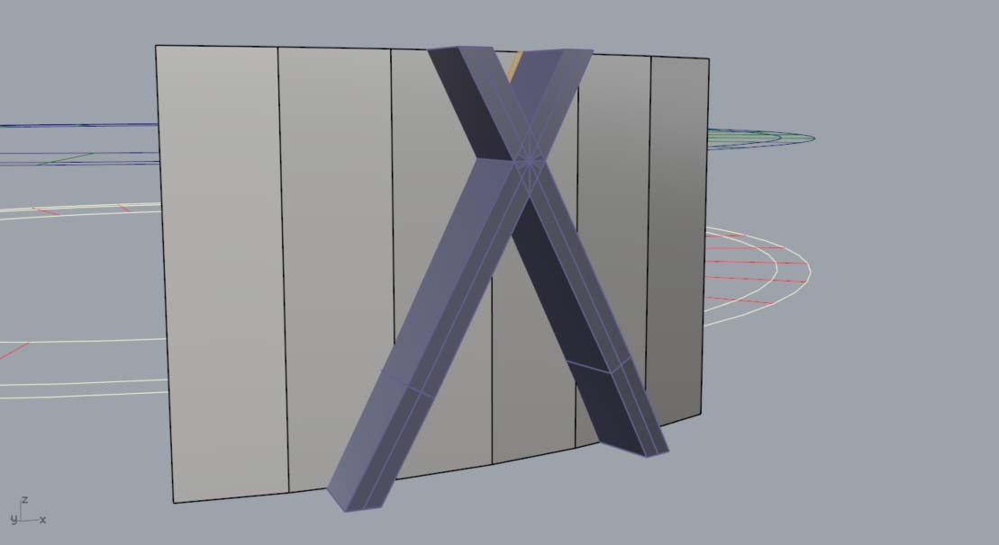
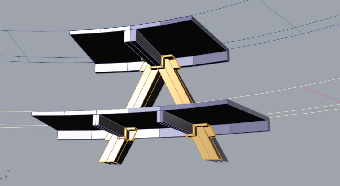
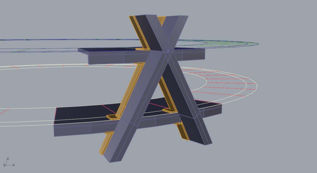
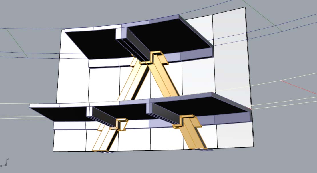
Dear @chris, Please see the images; reinforced concrete diagrid structure penetrates the curtain wall. To control the thermal bridging, some insulation applied.
I guess maybe the best way to estimate the local u-value is to define a number of horizontal sections and to calculate an integral (as you mentioned before)…
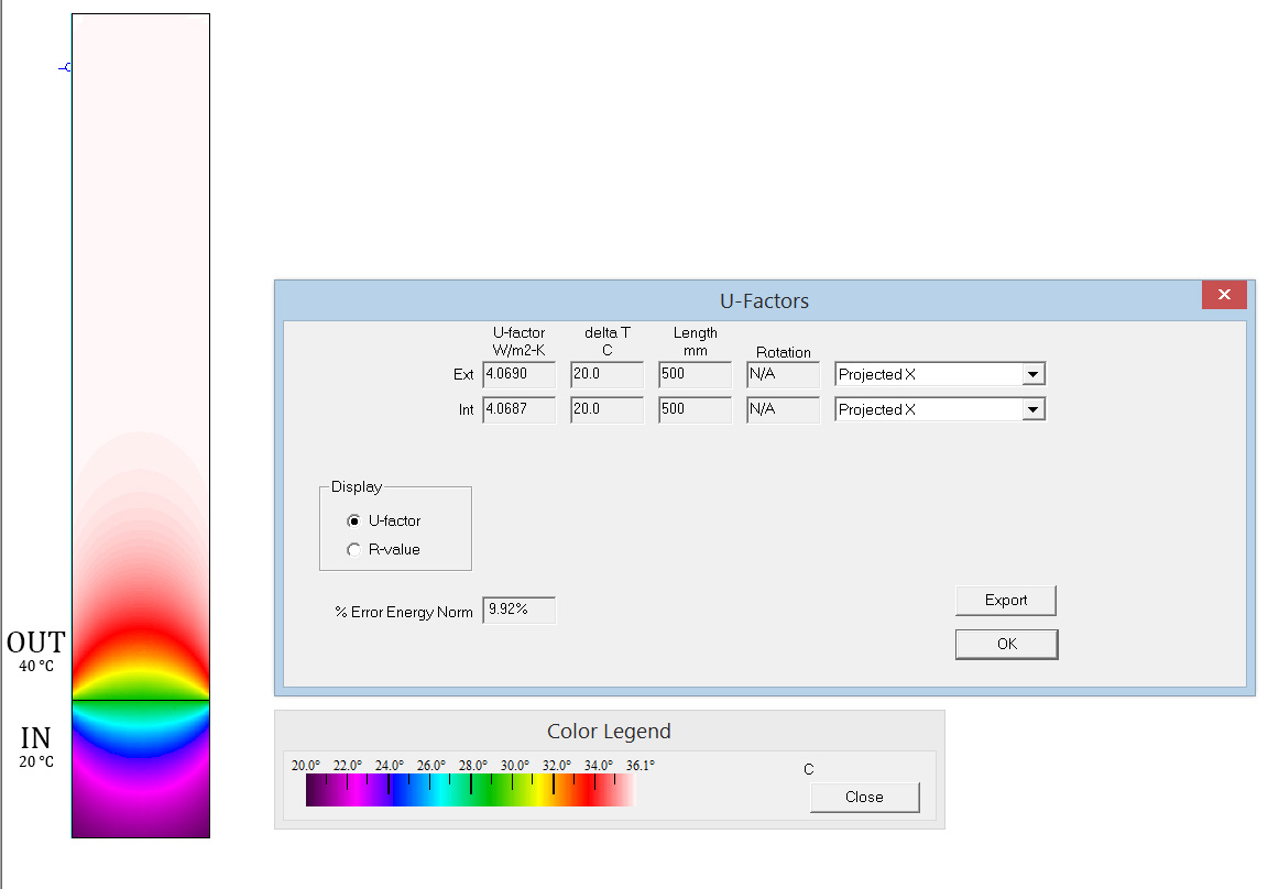
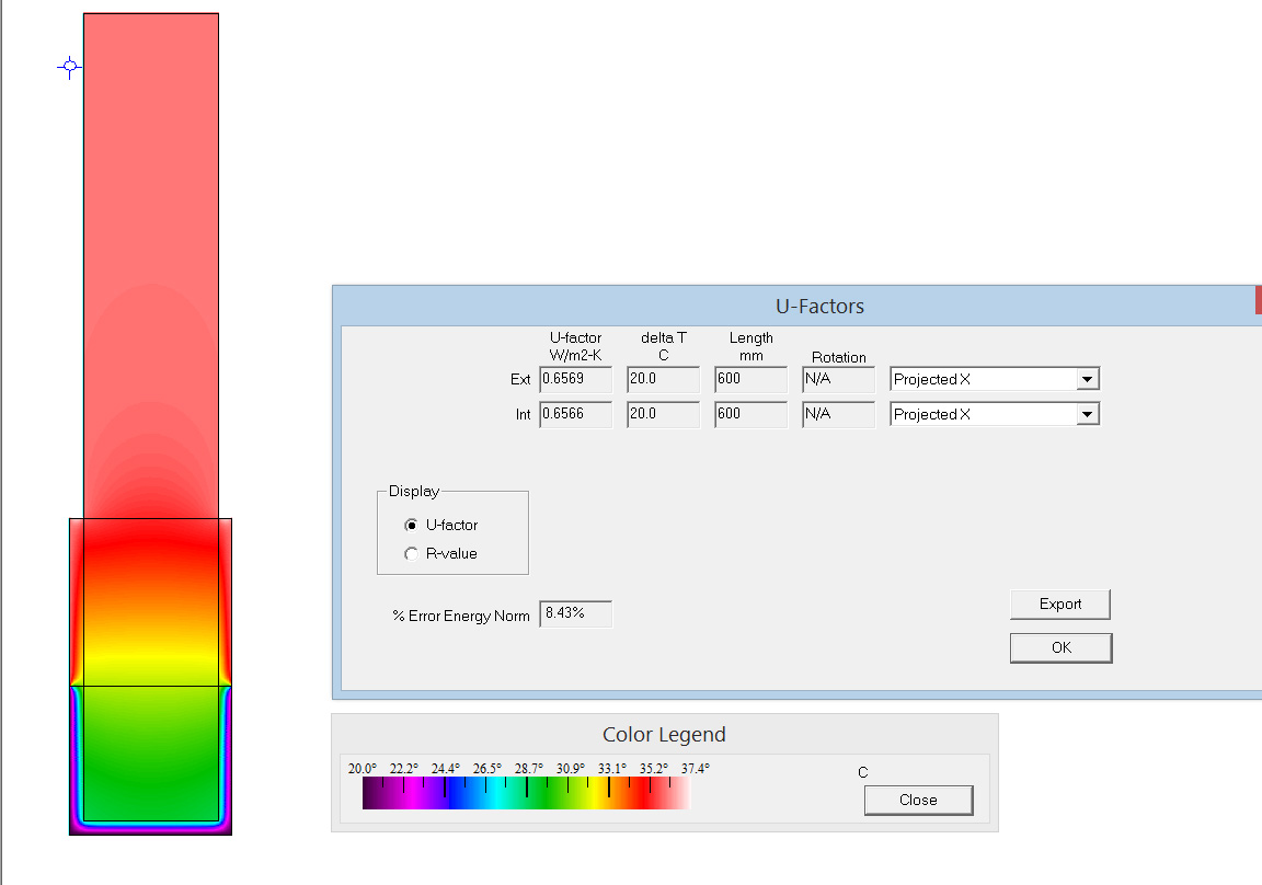
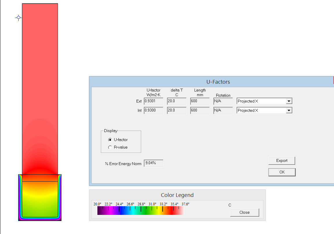
Previously for another study I tried to compare the u-values for different placements of insulation on a RC thermal bridge (they were all one single section though)… Are these similar to what you meant?..
@AryanShahabian ,
Thanks for posting the images. I imagine that roughly vertical slices within the plane of the diagrid members might be one of your best ways for estimating the bridging.
I also realized that there are actually two different methods that people use to deal with these situations: one that over-estimates the thermal bridging and another that underestimates it. The method that I have described to you tends to underestimate the bridging and is referred to as the “Parallel Planes” method. The other common method is to make only one THERM model but use materials that have area-weighted average conductances. This method is called the “Isothermal Planes” method and tends to overestimate the bridging. However, if you average the results of these two methods together, your result is usually pretty accurate (or at least accurate enough to be published in peer-reviewed reports)
Page 5 of the Thermal Bridging Research Report that my office produced a few years ago has some good sources cited for these methods:
I personally quite like the Chris’s solution, however in case you do decide to go down the proprietary software route: there is a Belgian company called Physibel which has a multitude of products for simulating 2D and 3D finite element heat flow. I believe it is less expensive than some of their competitors.
I have only used modelled orthogonal geometry with their software package Trisco. I believe however that it also allows you to model slanting edges. The importing capabilities are very limited though (only 2d DXF and BMP drawings). These limited capabilities mean that you’re often left with no other possibility then to manually set up the required grid and meshes, which can be really cumbersome.
The company also developed a software package called Solido which is more suited for complex geometry and allows you to import STL files. I haven’t tried this myself though.
Thank you both Chris and Samuel @chris the methods you mentioned are very helpful. @SamueldeVries I have a demo version of SOLIDO on my laptop. I sent an email to Physibel asking them if they could contribute to my research with a free temporary licence, but my email failed delivery. Maybe their email address has changed or the mailbox is full
 ). In my personal experience (and in the experience of many researchers), we have usually been able to get around this need for 3D by building several 2D models at different sections across the detail and then adding the heat flows of each section together. You can get these heat flows by multiplying each U-value by the “tributary area” that the section represents (I’m using an analogy to structural modeling here). Then, you divide the resulting summed heat flow by the total area of the tributary areas covered by the sections to get the heat flow through your full detail.