First of all, I am sorry if what I am asking has already been solved in another post. I have searched it, but I couldn’t find anything.
I am trying to make a thermal simulation of a simple room in a building, which has all the surfaces adiabatic except the facade, and a small gallery that I put in front of it in order to improve its behaviour.
As I want to be able to perform several simulations changing the constructions of the different walls, floors, etc. I have created the HB zones with surfaces.
My doubt comes when I try to solve adjacencies. Even if the component recognises the two walls (and its windows) as adjacent, it doesn’t erase one of them, so I have two walls in the same place. Does it have to be this way?
If no, I don’t know how to solve it. I have tried to simplify the process, erasing the surface names, erasing the windows and trying it only with opaque surfaces, but I always get the same.
If yes, then I don’t understand how do I have to interpret the results of the simulation, because I get two different surface temperature and two different opaque conductions from the same theoretical wall.
I wanted to attach the file, but I am a new user so I can’t… I hope I explained it enough.
You have a building that contains two zones, and two zones with one side overlapping. There are still two walls after using “HB Solve Adjacency” component.
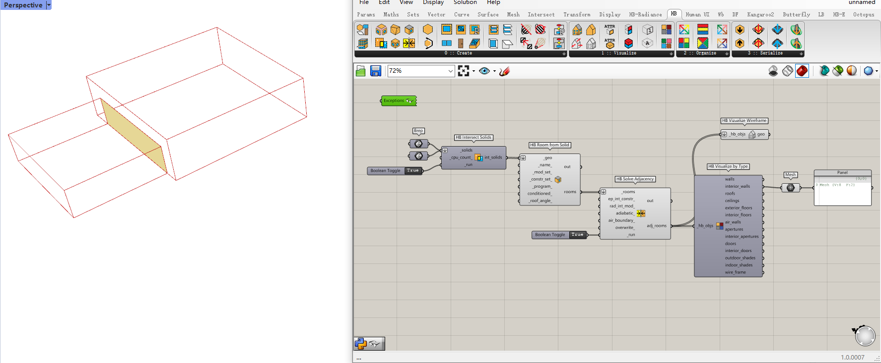
Do the duplicated surfaces between two zones have the same size? If not, you can try the “HB Intersect Solids” component before inputting the breps into the “HB Room from Solid” component. And there will be only one wall existing.
Thank you very much for your fast reply and so sorry for my delay. I’m new here, I’ll be more attentive from now on.
Yes, my two surfaces have the same size. And I also constructed the same windows in both of them, so that there weren’t any differences. Then I thought that this might be too complex and I also tried to do it with just opaque surfaces, but my result was the same.
I just discovered that I can’t attatch my gh but I can attatch one image, so I’ll try to explain it better now.
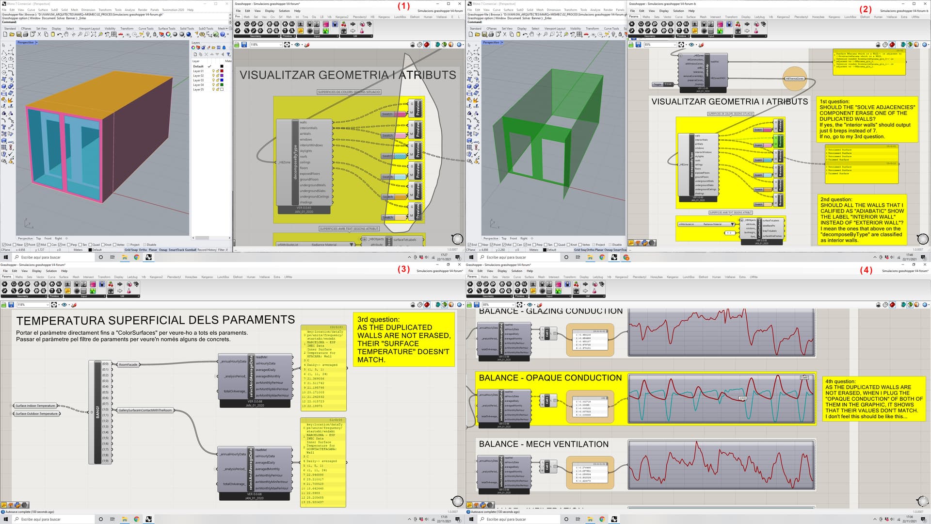
(1) When I visualize how gh recognises my geometry I get this.
(2) But what I’m pointing out is that it is still showing two surfaces on the overlapping side. And I am not sure if this should be this way.
(3-4) Because then when I check the results for the surface temperature or the opaque conduction, I get two different results for both of the surfaces.
I see in your image that you only get one mesh, but I have really tried everything and I can’t achive this… Coult it be because I am constructing the zones with surfaces?
Yes this is the expected behaviour. EP will interpret this as one wall and won’t duplicate the construction assembly during the simulation.
I think they’re the same wall, and the graph is just showing the energy balance on it’s two sides with some thermal lag. Try taking the monthly heat gain of wall 1, and compare it against the monthly heat loss of wall 2 (and vice versa). If they are approximately equal (with some tolerance for heat that doesn’t transfer across the surface), it’s the same wall.
Hi SaeranVasanthakumar! You are right!
I’ve compared the gains and losses and they are approximately the same. I’ve also checked the surface temperatures, and the indoor surface temperature of wall 1 is exactly the same of the outdoor surface temperature of wall 2 and vice versa. So yes, I think EP is not duplicating the wall.
So after this I have one last question. As in this case we see that the outer layer of the wall has a bigger heat exchange than the inner one (even if the daily average is the same for both layers, the graph shows more pronounced gains and losses), which of them should I take if I want to make an hour by hour balance of the room? Should I make an average of the two layers results or just take the inner one? How do you think that EP is considering the other walls (the exterior ones, that are not duplicated)?
Either way would work, ultimately the “balancing” will always work as long as you can comprehensively track the gains and losses, which in a non-steady-state system means tracking the energy in the thermal mass. If you take the outer zone wall as the boundary for a zone energy balance, then on a per hour basis, you will have to explicitly represent this thermal mass, in order to balance the energy terms. It may be easier, from a single-zone perspective, if you take the inner zone wall as the boundary, then you just have to track the energy transferred to and from outer wall as an external load, and not worry about representing the wall thermal mass, since the volume of the wall is outside your thermodynamic system boundary.
However, this will be complicated, due to the hourly basis you are tracking. The reason energy balances are typically calculated over longer time ranges (i.e. monthly or annual summations) is so that the minor differences due to thermal lag from the mass in the air and material are averaged out - essentially making it easier to represent a steady-state condition. Thus the easier solution to your problem is to simply to sum your energy terms over a long enough period that the energy difference due to your wall thermal lag becomes marginal. It may be difficult to dig into the EP custom results to make sure you are quantifying heat transfer in and out of various masses on an hourly basis (including, possibly the zone air).
Thank you SaeranVasanthakumar for your help!
I understand what you say and it is true that it is more convinient to calculate de balance over a longer time.
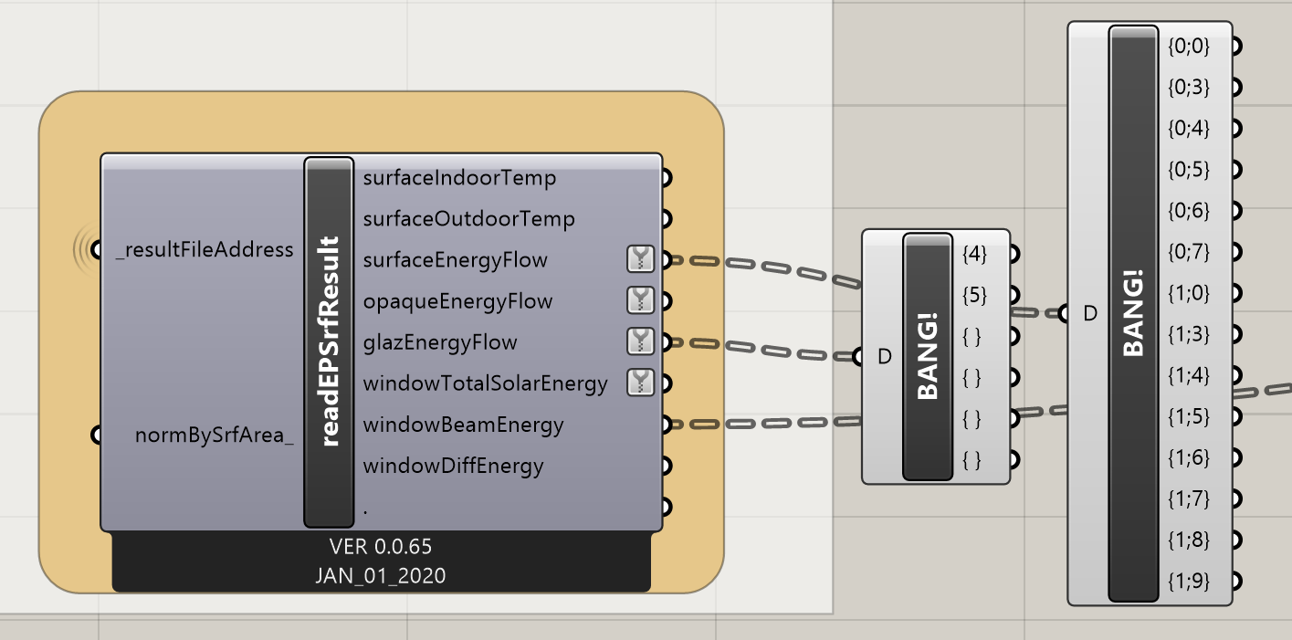
I am checking more things on the same file and now I see that I don’t get any results of energy flow through the interior windows, the ones that separate the room from the galery. Their branches only appear in the “surface indoor temperature”, “surface outdoor temperature” and in the “window beam energy” results, but in the last one they always get 0 as I defined solar distribution = 1 “full exterior” on the EnergySimPar. On the rest of the results in the “readEPSrfResult” box they don’t even appear.
Why is this happening?
There should appear the branches (0,1) (0,2) (1,1) and (1,2). Simulacions grasshopper V5 forum.gh (833.2 KB) my doubt is in the big yellow box
I continued the discussion here because I think it is probably related with the first issues. But it is my first time posting, so if I should open another discussion to make other questions, please tell me.
I think you should post this as a new thread. I’m not really familiar with how the data structure/report values for interior windows will appear in HB-Legacy. There’s a better chance someone else can help you if your question is not hidden in this unrelated discussion.
Update/correction: In hindsight, I think your approach of checking the surface temperatures like this is the right way to check for duplicated wall constructions. It occured to me today that checking conservation of energy through the wall, as I suggested, would actually give the same answer in a scenario where you accidently did create two internal walls adjacent to eachother, since they would act as a single mass.
 I hope I explained it enough.