Posting a question to all community. I am trying to understand the effect of a projecting concrete slab (like a terrace or a balcony) w.r.t. the thermal mass and its impact on affecting the slab temperatures in the interior of the building. I know that with E+ we can simulate the average surface temperatures, but is there a way that we can simulate a detailed temperature profile of a slab over the course of the day for few days/months ?
Are you looking for something like this?
https://bigladdersoftware.com/epx/docs/8-1/engineering-reference/page-017.html
Mostapha,
This does seem similar to what I have in mind, though to be honest, I did not yet clearly understand the output from the method. I am literally looking at THERM simulations but that can run over the course of day/weeks and account for both the solar radiation falling directly on the surface and the diurnal shift in temperature thereby cooling the slab in the evening.
The reason we are trying to understand this is to make an educated decision if thermal bridging in the balcony slabs affects the interior MRT in hot climates or not and by how much.
Hi there,
It might help to clarify your questions. From what I can tell, it seems that your questions are:
- Does the thermal mass of a balcony increase or decrease the thermal bridging to the slab?
- Does the heat transfer to the slab negatively impact thermal comfort through increased MRT?
The deltaT between air temperature and floor temperature that results in radiant asymmetry needs to be roughly 12F for 10% PPD and 18F for 20% PPD. (2017 ASHRAE Fundamentals Chapter 9 and 2013 ASHRAE 55) Be aware that these statistics are for a warm ceiling, which may be the case for a multi-story building with this balcony condition repeating. Does your thermal analysis or gut-reaction about your building and climate lead you to believe that your floors or ceilings may be 12-18F warmer than indoor temperature?
I would also challenge you to think about the balcony’s heat exchange conceptually. It is most likely exposed on five sides to both daytime and nighttime temperatures (and sun too). Depending on the diurnal swing, the balcony may in fact be a source of thermal heat loss at night. In some climates and building programs, you can think of your balcony as a fin extending out from your building much like the thermal sink in an LED light - drawing heat out from your interior spaces through the slab bridging. It’s hard to gauge how it will perform in your climate without knowing details but hopefully this helps get you thinking conceptually if simulation is not possible.
Thanks, this is in line of our thinking too. I should have provided more information that will clear out the question more:
Climate - This is for Delhi, India. The cause of concern for me is the summers when the temperatures are >90/95 for good 2-3 months. The night time temperatures don’t drop <70 in these days. That means a high chance of the concrete slab being “saturated” with heat (even if we consider night cooling) and be around 80 degrees average over the course of 24 hours (conceptually).
The program is an office building, so we might be looking at the HVAC turning down around 6-7 PM.
As far as the thermal comfort goes, the top slabs can very well be above that threshold of 18F delta T. but I have a feeling that the other floors also could face that problem. The slab that we are designing will act as a shade to keep the glass temperature down, but conduction gain would be high.
I think @KitElsworth’s line of inquiry is the best way to tackle this problem. But to continue the discussion on your earlier question of how to model the temperature profile of your slab, I think the Conduction Finite Difference (CFD) approach (linked above) would be the best way to achieve an accurate simulation of heavy thermal mass.
To give some background: THERM is a 2D steady-state heat conduction modeler, (as you probably already know!) so it won’t capture the diurnal temperature swing in heavy thermal masses you’re looking for. For transient-state heat conduction you can use EnergyPlus. In Openstudio (and I believe Honeybee) the default heat conduction algorithm is the ConductionTransferFunction (CTF).
I have to admit, I still don’t quite understand the CTF algorithm, but I’ve been told it linearly relates heat/temperature surface conditions to a history of surface conditions. Therefore it eliminates the need to solve the heat transfer within a building element. This is very computationally efficient, but for a thick thermal mass where the temperature profile changes according to depth within the material, you can see why this method can start to cause inaccuracies. Caveat, as said earlier I still don’t quite understand the calculation here, so perhaps this can still be a adequate way to model your bridge.
However, the CFD in contrast explicitly converts your building element into discrete layers in 1D, to model the heat flux through different depths. So I think this algorithm would best model the diurnal shift in temperature for a heavy slab material. And the output will be the same as what you are getting from Honeybee now, because all you’re doing is changing the way your temperatures are being calculated. Specifically, once your OpenStudio simulation is done, you will be able to extract the surface temperatures for the heat slab and inspect the temperature profile of your thermal mass.
However, setting this option might a little bit more upfront work, as I don’t see it exposed as a parameter in the HB components.
-S
@SaeranVasanthakumar I agree with you. I know the limitation of Therm (and wish that in the future there would be a way to model this problem in a similar manner).
To be honest, I don’t necessarily understand completely the algorithms myself and will be doing this reading over the weekend.
@mostapha - would like to know your thoughts on the best way to answer this question.
I am also being told by some people that software like EDSL TAS are able to calculate the surface temperatures more accurately. Anybody has any idea on that?
Question to all. I just tried something. I made 2 HBZones using a single brep (8 meters high and dividing it into two floors). Then I made all construction adiabatic except the floor slab. Then I added a projection in form of a room on the upper level, but made all walls and roof of it as “Air Wall” This means now on the entire model, only slab should be the conducting element? I am getting some results that show that the thermal mass flattens out the interior slab temperature. I am still running more studies, but wanted to know from you guys if this technique even stands good or not?


I had a more or less similar question but couldn’t find a clear answer to it.
From what I heard, seemingly there are only a couple of doctoral dissertations in mechanical engineering which explored the topic, their methods haven’t been integrated with energyplus yet though.
I think the E+ method you have with the air walls is a bit problematic since these air walls act as radiant barriers. If anything, it would be a better approach to model the surfaces with half the thickness of the actual slab construction and drop the height of the zone to the thickness of the slab.
All of this taken together, I think that the best approach is to build a THERM model with boundary condition inputs that represent the average conditions of the hot time period that you are interested in. Given that the slab has mass, the conditions that you are trying to observe are only going to manifest themselves over long periods of time and these long periods make the steady state assumption of THERM truer to what will actually happen over time as the slab becomes saturated with heat.
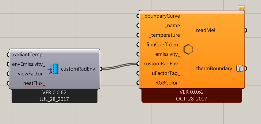
Note that, by average conditions, I mean average outdoor temperature in the hot period and average solar radiation that falls onto the slab (including both night and day). You can set solar radiation on boundary conditions using the heatFlux_ input of the Custom Radiant Environment component:
I will also add that there will be a new version of THERM by the end of this year that will be capable of modeling transient heat flow calculations over an entire year. This will help a lot with estimating moisture potential and other transient phenomena in light non-massive constructions. However, because your slab is massive, I don’t think that a steady state calc will still give you a a good understanding of what will happen with your design.
Please correct me if I’m wrong; I guess there’s a problem with defining two parallel surfaces (each with half the slab thickness). These surfaces are horizontal. Thermal conductivity of surfaces in E+ are 1D which is like a normal vector (vertical). But the thermal mass effect with the interior space is in other direction (horizontal).
Regarding THERM boundary conditions and film coefficients: could you please share some example files or links to probably existing online tutorials?
Thank you