Electric lighting question

Hello all,

I am trying to do an ULR (Upward Light Ratio) analysis of some sorts. What is really specific and I can’t find the answer for online, is, how(or is it possible) can I set my Lights, or IES files, or the test grid to only take into account the DIRECT light coming from the source(electrical lights)?

Has onyone done an ULR study using Honeybee and Ladybug and has some advice or information?

Thank you all,

Hristo

Me again.

I have been playing around with my model and the settings in HB, trying to get a result. During this time several questions popped up.

1.I am using HB 0.0.65. Should I upgrade to the latest version?

2.I have my model and lights assigned, but there is something I dont understand completely. I have a closed solid as my building volume and open poly for my perforated facade which I convert to HB_createHBSrfs. Is this the correct way and geometry to use? When is closed poly, open poly or mesh used?

  1. I am trying to achieve an Upward Light Ratio analysis and after reswarching on the web I decided to build a box around my geometry and use its surfaces as test grids to get the data for any light going beyond my geometry. Will this strategy work for my needs?

4.At first, using the box around the model, I didnt get any results on the test grids(the box walls). If you use more the one srfc for a test grid, what is the correct way to assign them in HB?
After not getting any results on the test surface, I built 2 surfaces directly infront of my lights, which produced a result mesh.
Could the distance between the “Box” and the lights make it so I dont get any results on that “Box”?


5. I then decided to rotate my lights 180 deg so that they face away from the geometry(green lines are lights with a 60 deg beam facing away and magenta are the ones facing the model). The results I got were the same as before. How is that possible when the light is facing the other way?

6.When I tried to run the Electric Lighting Example, using meshes for my building volume and facade elements I get strange spotlights, as if some of the lights are “outside” the perforated facade. Why am I getting these results?

Sorry for the handfull! I will appreciate any help or advice! Thank you!

Hristo

Also, it doesn’t seem to matter which way me lights are facing(green and magenta lines on first pic), I get the same results for the box geometry, which is ver puzzling.

Hi,

Set the -ab value in radParameters to 0. That way all the reflections are turned off and only direct contribution is considered.

With ab - 3

With ab -0 (everything else remaining the same).

Regards,
Sarith

PS: I didn’t check your second and third posts (yet), however, I hope this cleared things somewhat.noReflection.gh (503.7 KB)

Thank you very much @sarith !!!

I will try it right away.

Hristo

Hi @sarith , really sorry for buggin you, but have you had the time to check on the other problems I had?

Much appreciated,
Hristo

Hi @Hristo,

I don’t think it matters because the electric lighting components haven’t been changed since Jan 2016 or so.

Mesh works much better for geometry that is not conventionally polygonal. Meshes, when converted to Radiance RAD format are converted as triangles, however, the triangulation achieves much better shape conversion (from native Rhino geometry to RAD) than traditional BREPs do.

For the rest of points, what specific application is this simulation meant for? Is it street lighting or facade lighting?

As a general note, encapsulating your geometry inside a box to intercept stray lumens should work in theory, however, since far-field photometry (used to generate IES files and something that we still use) is predicated upon the assumption/adherence of the Five-Times rule (see under “Point-Source Approximation”), your results might be off by quite a margin. Although software like AGI32 and Dialux try to address this issue by using Adaptive-Subdivision (or some such algorithm) to discretize luminous sources and scene geometry, the results are still off when it comes to applications where the sources are close to the geometry.

In Radiance, and therefore in Honeybee, discretization of the source is controlled using -dc, -dj, -dt and -dr (if I remember correctly).

I am sorry for the delayed reply. It might be a while before I can get back to the forum.

Regards,
Sarith

Hi @sarith , no need to apologize, I appreciate that all of the guys here take the time to help people in need. Your answers and links provide very useful information.

While playing around with my model I came to a discovery. When I have my model oriented “correctly” having my lights point in somewhat of an upwards direction I get no results on breps that are above them, even if I have changed the surfaces direction to point towards the lights.

If I rotate my model 180 deg and run the same simulation, I get results on the same brep.

What is the explanation here?

Thanks to everyone,

Hristo

Oh, and as for the simulation type, I am trying to do and Upward Light Ratio, in order to see in which category will this building fall into.

Hello again,

I’ve been continuing to play around with LB and HB-Legacy. At some point after installing Radiance 5.3 I started to notice that the FalseColor is only displaying blue, no other colors. I also noticed the missing legend but found the solution to that problem here in the forum.

Why am I getting the same blue color everywhere, what am I missing? Is it something to do with the way I set up the file, or some new Radiance 5.3 settings I haven’t done correctly? I can see I have the falsecolor2 app installed in the Radiance folder, I think I remember reading somewhere it comes pre-installed with 5.3.

Several other question came up:
1.Is there any other setting to increase the quality of the output images we get, except for setting the quality int to 2 and increasing the img Height and Width?

  1. Is there a way to use some sort of additional light to make the whole of the volume visible, not just where the set lights light it up?

Thank you very much for the support!
Hristo

Hello again!

starting to feel like I am talking to myself!

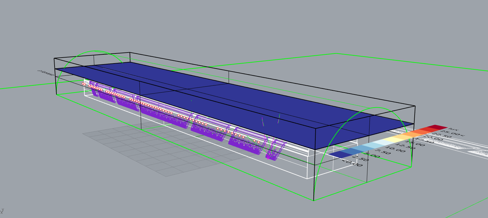
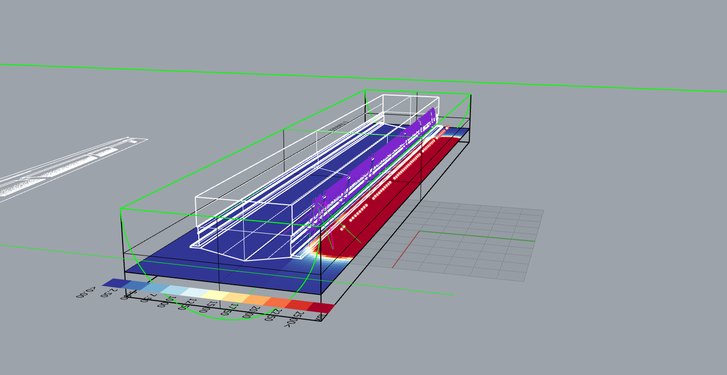
I found the Rendering Options and started testing them out, boy was that fun! However there is something that appears to be out of my control. I get two completely different results in a sense of visual feedback. I am really trying hard to understand why is this happening and how can I control it?

I have run multiple renderings using, comparing and studying different settings in the script, as well as playing with the actual 3d model(having separate meshes, joining them, moving light source further or closer).

So here, the actual problem.


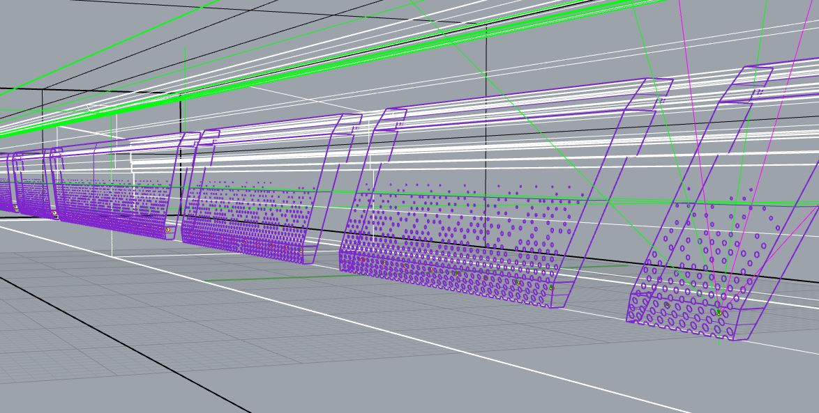
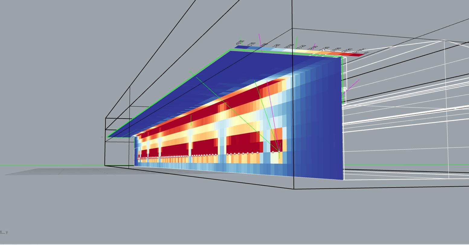
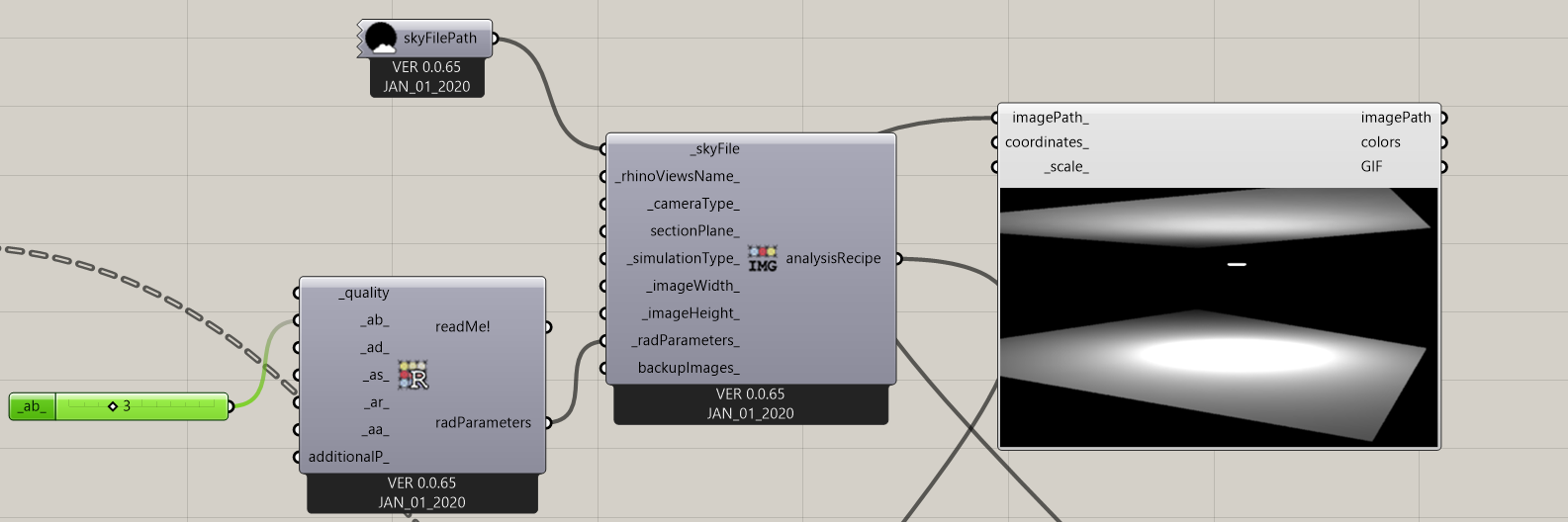
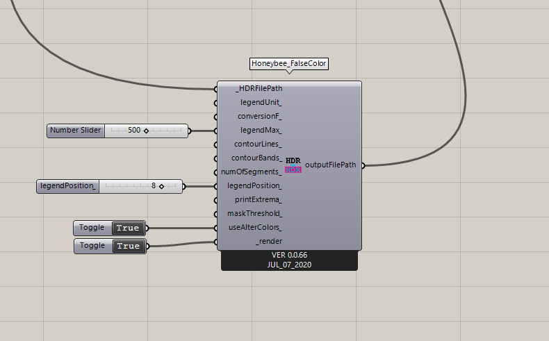
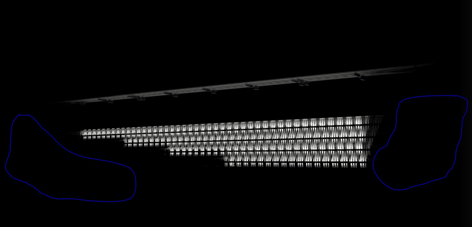
This is the result I would like to get, and have gotten once, but am unable to recreate again.

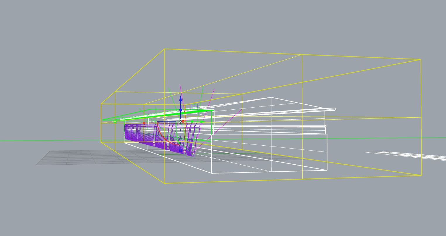
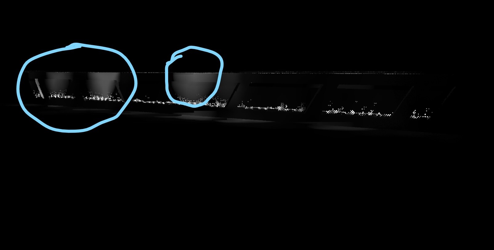
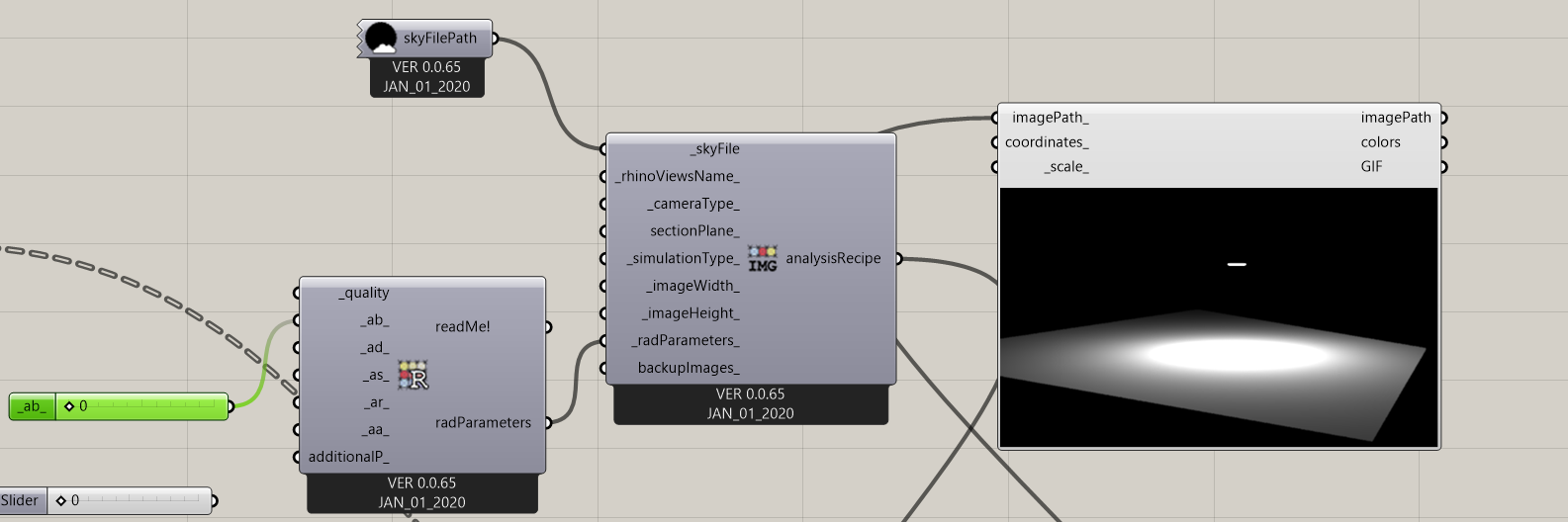
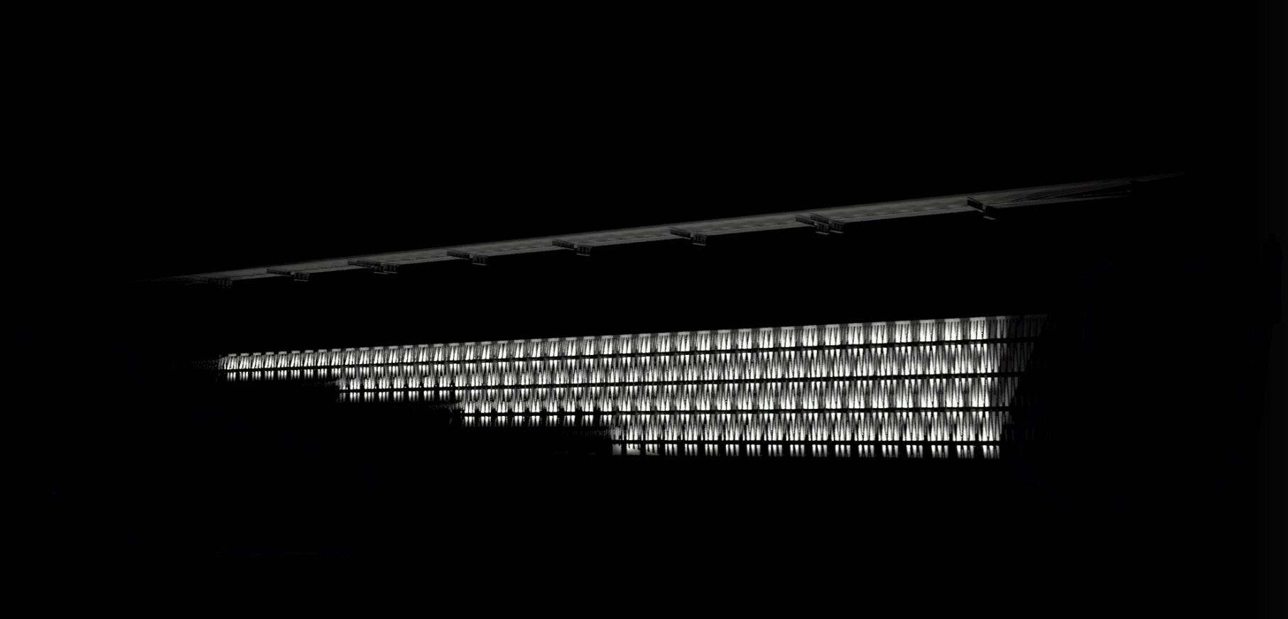
This is the result I commonly get. I can see why I get the bright spots, having some reflectivity to the scene with the -ab set to 2, and also it appears that the main facade geometry is missing. This leads me to believe something goes wrong either with the model, or params given to the geometry afterwards.

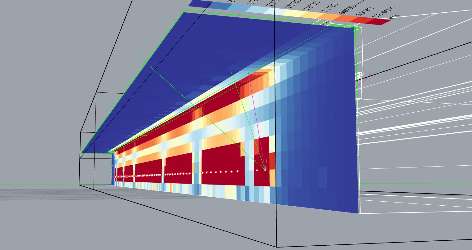
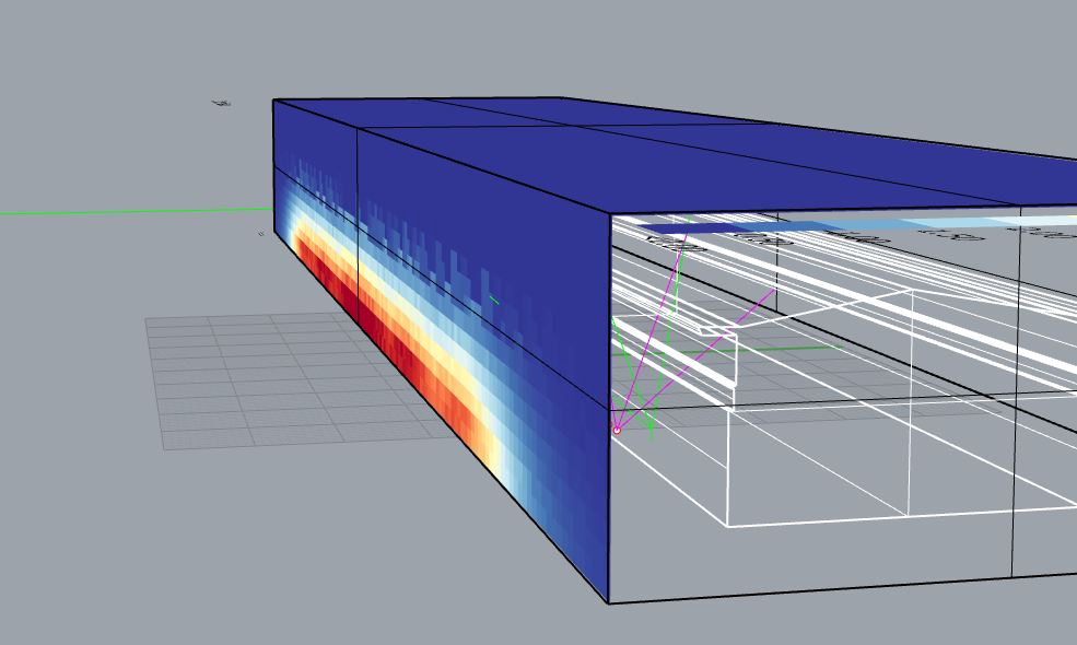
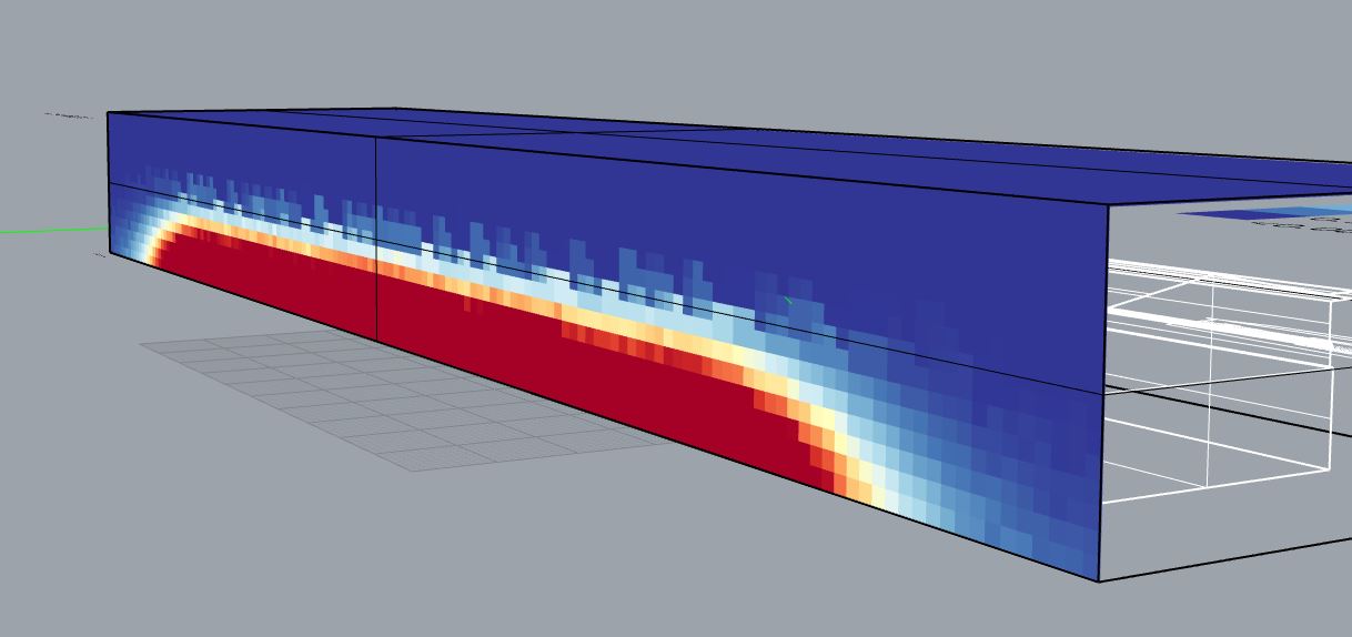
Here, the rendering with -ab set to 0

I will be very thankful for any input you might have!

Also, on a side note, I get this very annoying occurrence, when I type commands in GH, Rhino starts recognizing them in its command prompt and I am unable to type in GH.

Big thanks to everyone who has contributed to my problem solving, your help is and will be greatly appreciated!

Hristo

One more question, the way I approach linear lights is, see what dimensions are given in the specific .ies file, and divide the lenght of the linear light by that, so that I get points to which I assign that .ies. Is that the correct way to go?

Sorry for tagging people, I get that all of you have more important things to do, but if you can spare some time, whenever, it will help me out a lot @sarith @chris