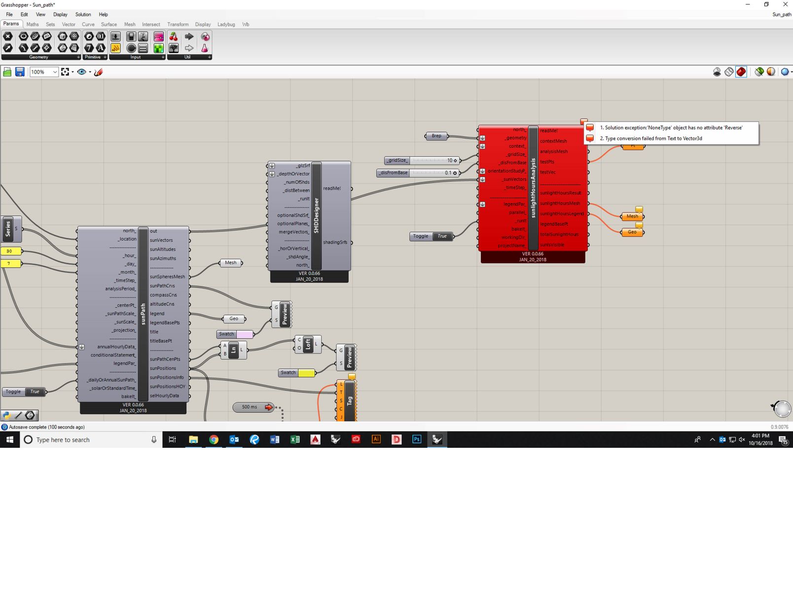
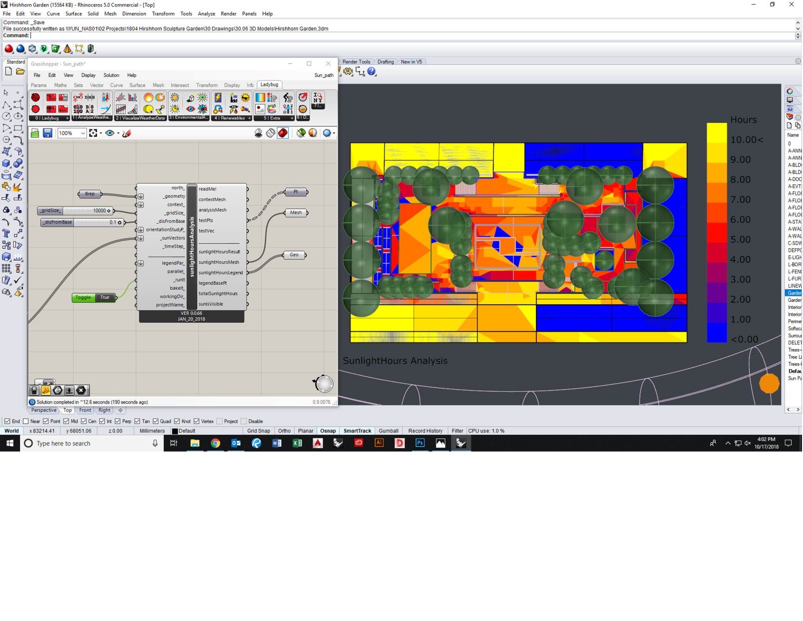
I’m extremely new to Grasshopper and Ladybug and am attempting to make a sun path diagram of an architectural model. I have followed Mostaha’s videos but am stuck on video 3 of 3 as I am getting an error when I try to link the sun vectors from the Sun Path panel to the sun vectors from the sunlight hours analysis panel. I’ve attached a screenshot here. This sounds like a similar problem to Misung’s post but I am not getting any solution from the answer you gave her. Any help would be very much appreciated.
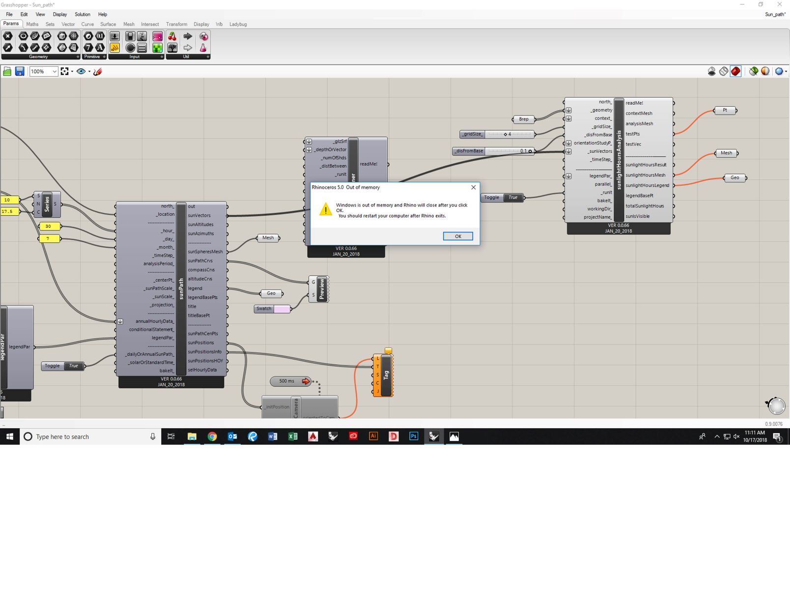
I see, ok, I changed this but now when I connect sun vectors to sun vectors, Rhino crashes and I get this warning (pictured in attached screenshot). This has happened a few times now. Could it be crashing because there are errors on the Sunlight Hours Analysis Panel?
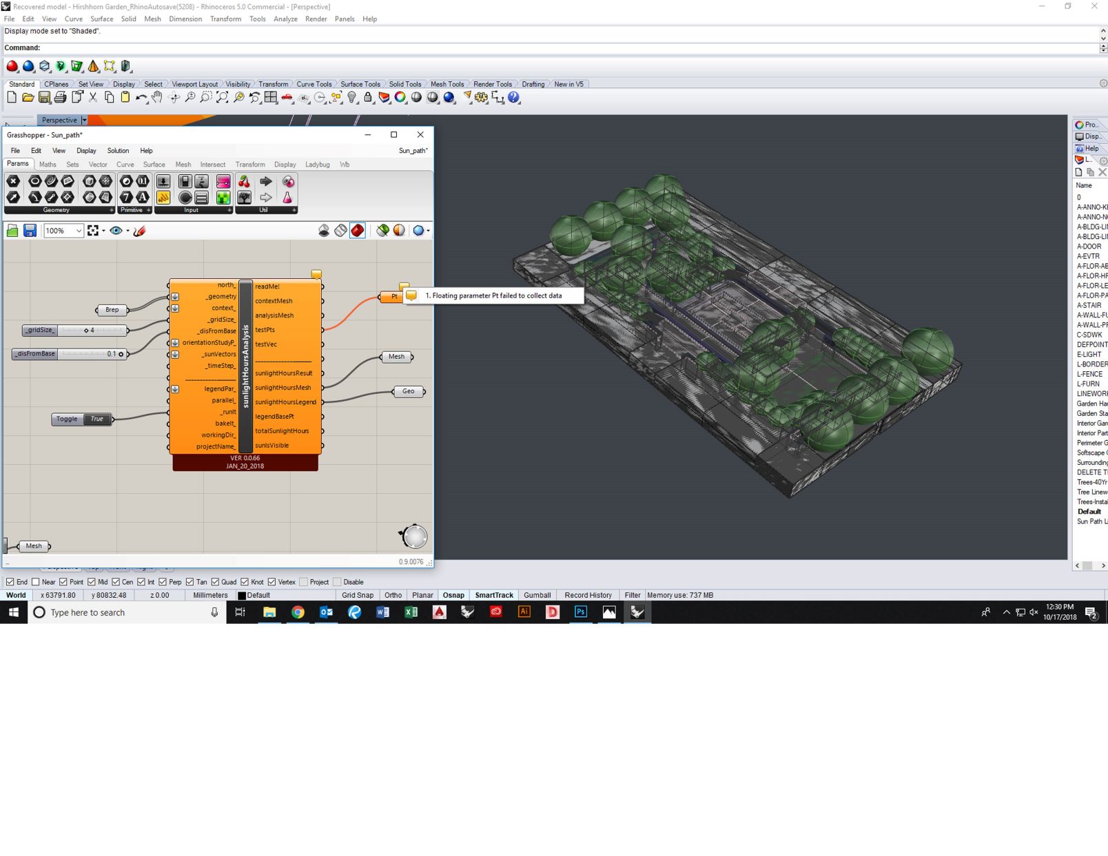
Yes, the model is in metric. I don’t know how to find the number of test points, but I do know that the test points panel is getting an error as shown in attached screenshot. Could it be there are too many test points? How do I change this? I also noticed that the 3D model seems to have this dark grey screen over it, I’m not sure if maybe the test points are making the model dark grey?
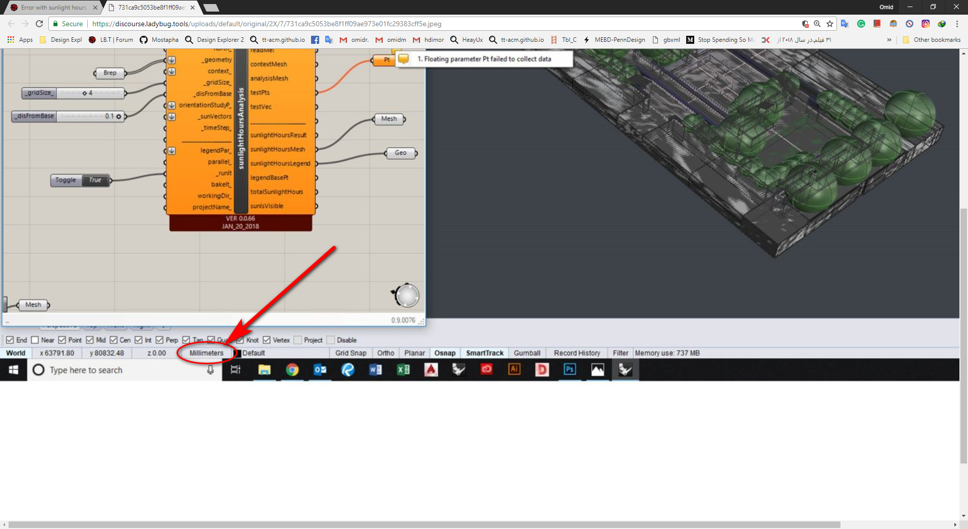
But I have been intentionally modeling in millimeters, do I have to change the units to meters and scale it accordingly in order for the sun path to work?
No! But you should input the grid size according to units of your model. You’re currently calculating the results for every 4 mm. See your input for gridSize.
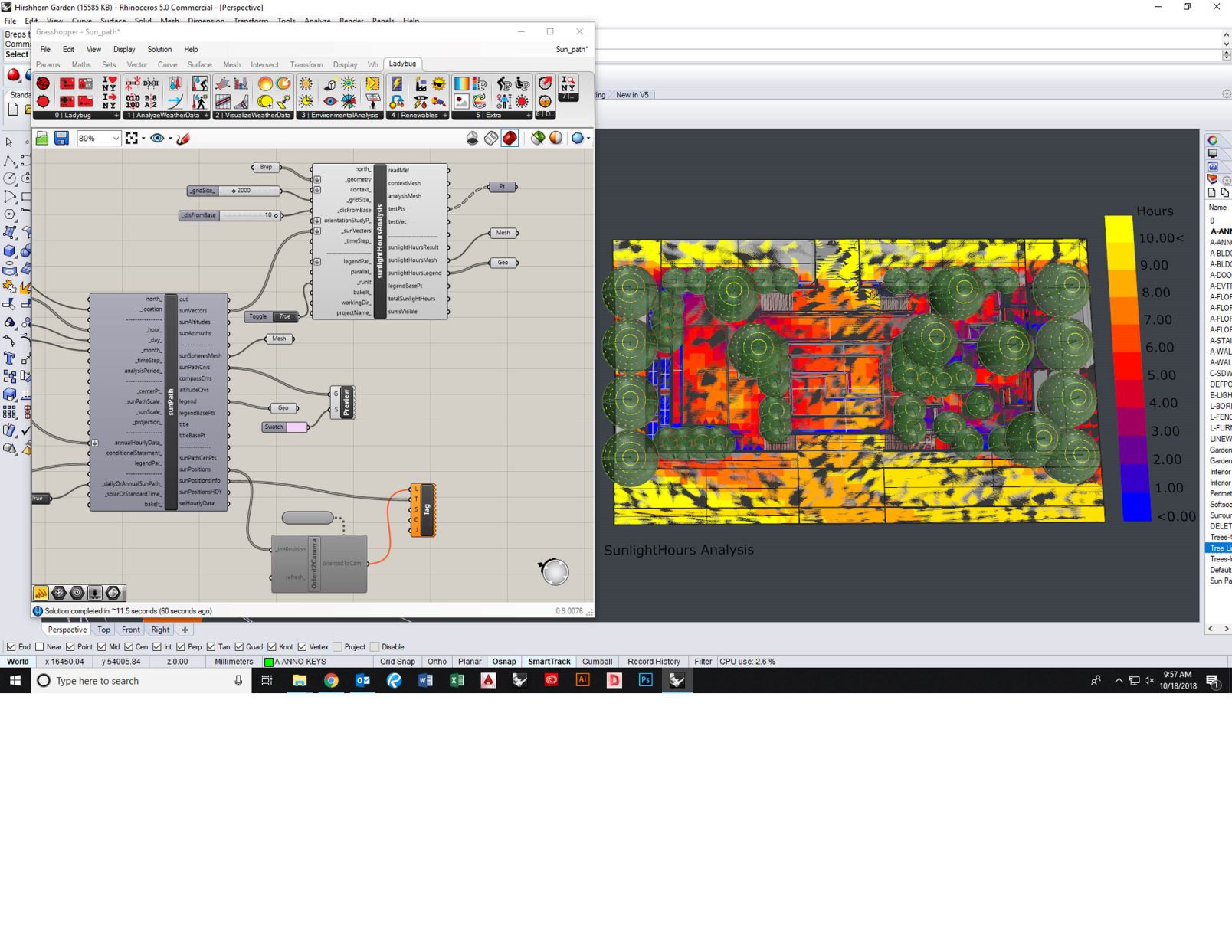
Ok, I managed to fix the grid size while keeping the units as millimeters. But I am now seeing an outcome that does not look like the sun path diagram you produced in your videos on this topic. Do you know what the problem could be?
Thanks so much for your help on this, I really appreciate it. I changed the grid size and set point to the values you both recommended and I went into the model and flipped directions of surfaces but I am still getting this very strange graphic when I connect the sun vectors wire. Any other idea what the issue could be?
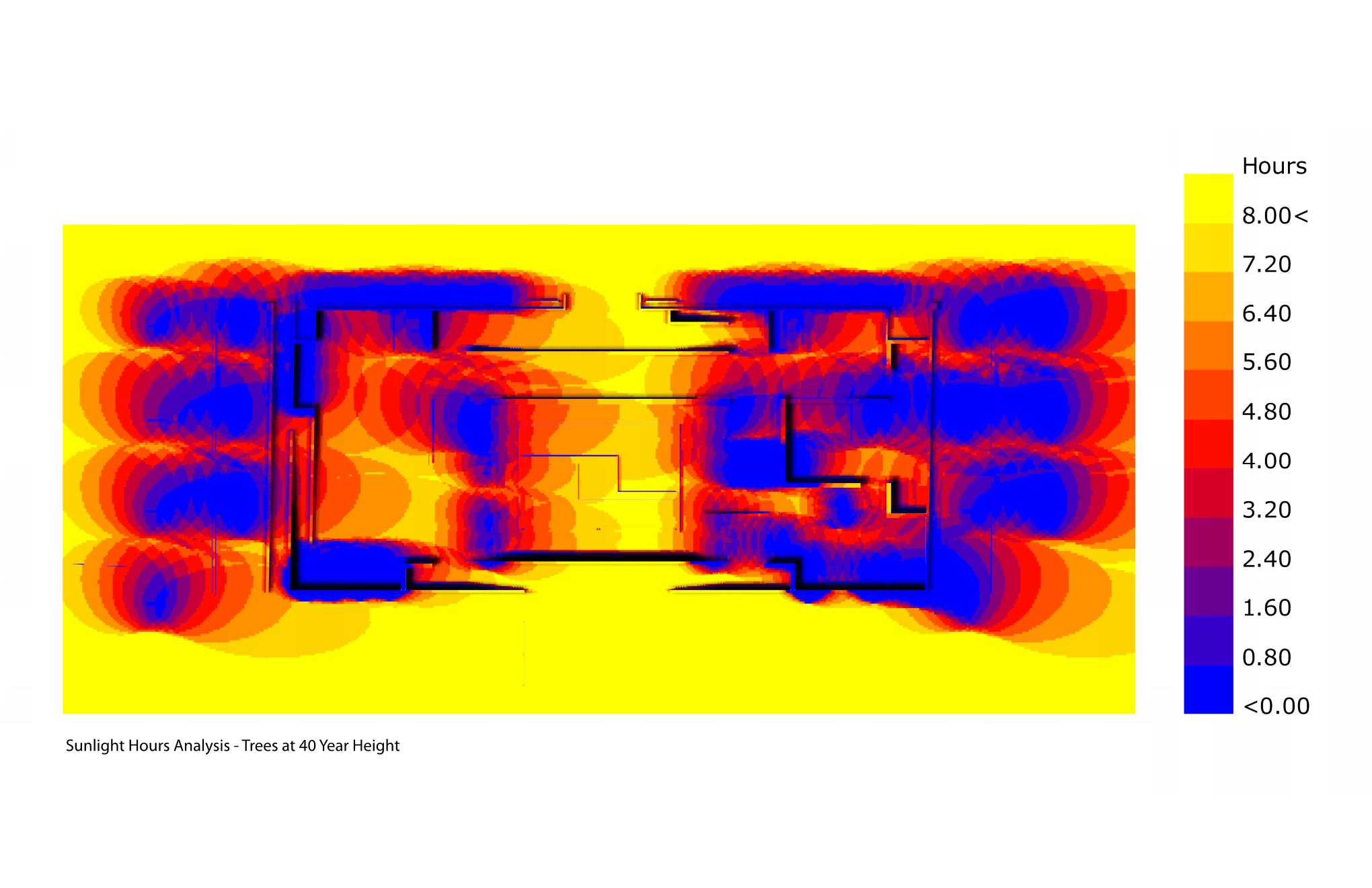
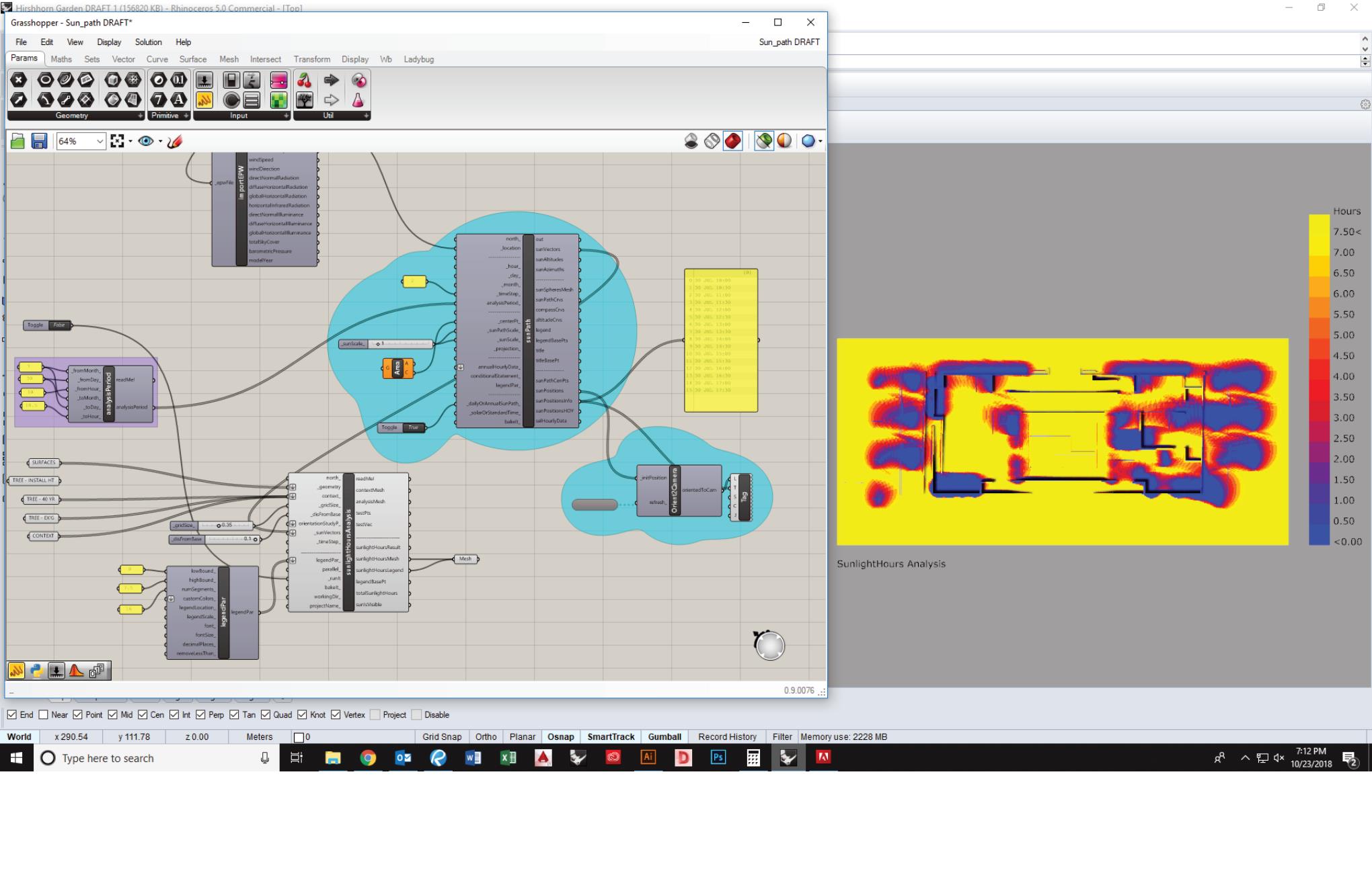
Thank you for your help, I finally figured out how to run the sun path but now I am having an issue with the legend. I ran the sun path and it looks correct (image 1) but then when I adjusted the legend to get the number of hours and increments I wanted, the sun path diagram looks incorrect and distorted (image 2). Basically I want the diagram to look like image 1 but with the legend from image 2. Does this make sense / is this possible?