Finding the difference between two models?

Hello! I wonder if someone might have any ideas about how I can find the difference between two models? Details below…


Scenario:

I have two E+ models. One is a ‘reference’ model created by someone else, and the other is a Honeybee model which I am creating. My goal is to match my honeybee model to the reference model’s outputs, as closely as I can.

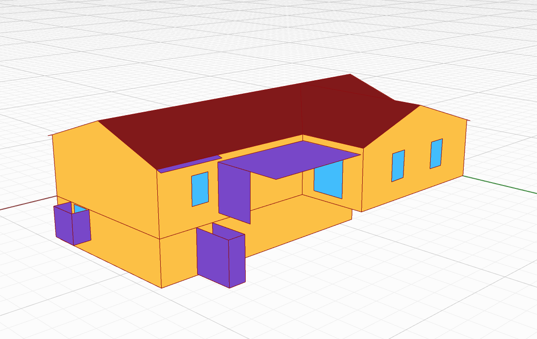
The model here is for a ‘power-outage’ in winter, for a single week. So the simulation is setup to run for a bit, turn ‘off’ for the outage week, then turn back on. Both simulations use IdealAirLoads. The building is a single zone, two story single-family home.


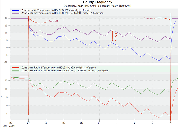
For some reason, I cannot get my honeybee model results to match the reference model, and I am running out of places to look and things to try… The graphs below show the ‘reference’ model results, and my honeybee-model:

Weather/Climate:

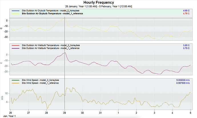
:white_check_mark: Both models have the same outdoor dryblulb, wetbulb, wind-speed, etc…


(Note the weather is complicated… the reference model does internal processing to adjust the weather during the E+ run, however I have been able to match this in a pre-calc process. Anyway: I have two weather files, one for each model, and they appear to match now, as shown above)

Internal Loads:

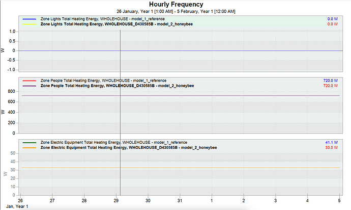
:white_check_mark: People, Electric Equipment, Lighting at all the same in both models:

Solar Load:

:white_check_mark: As far as I can tell, the solar load is the same in both models:

Ventilation:

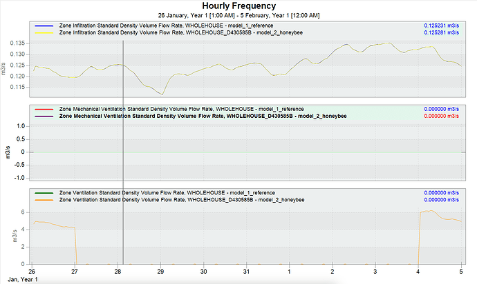
:white_check_mark: The ‘Ventilation’, ‘Mechanical Ventilation’, and ‘Infiltration Ventilation’ all show the same flow-rates in both models:

Envelope:

:white_check_mark: I have reviewed the .html outputs as well, and from all I can see the envelope assemblies are identical as well. There is some known discrepancy as the ‘reference’ model uses Kivy for the soil while Honeybee does not, but that is minor (I think?).

I have also double-checked all of the surface areas to ensure that the model geometry is the same in both cases.

Indoor Air:

:x: but… even with all of those items above identical, I still get very different results between the two models for air-temp, radiant-temp, and humidity, and I can’t figure out why:


So… I am wondering: what else can I check? What else might I take a look at to see if I can find the culprit here? Anything come to mind that I am clearly missing or might investigate further?

I am struggling to find where the additional discrepancy might be between the two models? I have tried to review the various output-variables, but I cannot find anything which would account for this difference?

any thoughts or suggestions are very much appreciated. I’m losing my mind a bit trying to track this one down…


relevant files attached for reference:

thanks!
@edpmay

Hi @edpmay, there is a tool called ‘EP-Compare’ in the eplus directory:
EnergyPlus-24.2.0\PostProcess\EP-Compare
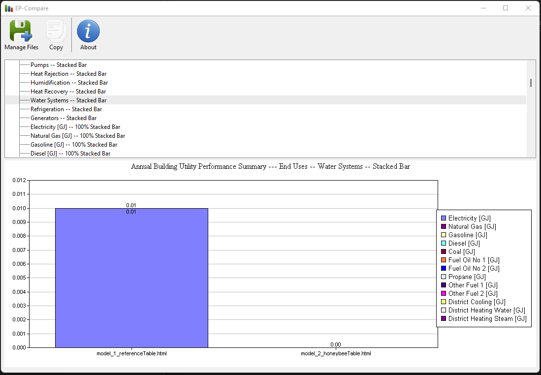
That lets you compare pretty in-depth with the choices, but lets you compare the two models really well, for instance the missing water end use for model 2


I just wanted to share as I’ve found the tool helpful in comparing models
best
-trevor

2 Likes

Hi @edpmay

I compared the two IDF; it seems there is mismatch, leading to this difference as below:

For defining the building in general:

The first idf is:

BUILDING,
test_full_GUI_outputs_M_10W-20S_StateCollegePA_BASE_NV, !- Name
0, !- North Axis {deg}
City, !- Terrain
0.04, !- Loads Convergence Tolerance Value {W}
0.4, !- Temperature Convergence Tolerance Value {deltaC}
FullInteriorAndExterior, !- Solar Distribution
25, !- Maximum Number of Warmup Days
6; !- Minimum Number of Warmup Days

While the second IDF is:

Building,
revive_test_model, !- Name
0, !- North Axis {deg}
City, !- Terrain
, !- Loads Convergence Tolerance Value {W}
, !- Temperature Convergence Tolerance Value {deltaC}
FullExteriorWithReflections, !- Solar Distribution
, !- Maximum Number of Warmup Days
; !- Minimum Number of Warmup Days

For the simulation control:
First IDF is:

SIMULATIONCONTROL,
Yes, !- Do Zone Sizing Calculation
Yes, !- Do System Sizing Calculation
Yes, !- Do Plant Sizing Calculation
No, !- Run Simulation for Sizing Periods
Yes, !- Run Simulation for Weather File Run Periods
No, !- Do HVAC Sizing Simulation for Sizing Periods
25; !- Maximum Number of HVAC Sizing Simulation Passes

second IDF is:

SimulationControl,
Yes, !- Do Zone Sizing Calculation
Yes, !- Do System Sizing Calculation
Yes, !- Do Plant Sizing Calculation
No, !- Run Simulation for Sizing Periods
Yes, !- Run Simulation for Weather File Run Periods
No, !- Do HVAC Sizing Simulation for Sizing Periods
; !- Maximum Number of HVAC Sizing Simulation Passes

The materials used for these 2 simulations for the building envelope are totally different. For example, the second IDF does not have an F08 Metal surface.

I see also zone ventilations are totally different, for the first building, it uses autocalculate while the second has some specific values.

Importantly, zone sizing methods are different. You may search Sizing:Zone, in both files to see the difference.

For the Fenestration, it seems the 2nd idf has more details for the control.

Probably the 2nd IDF is produced by HB since it does have lifecycle details, and the first idf is formulated with other software I guess

I suggest doing some text parsing in Python with these 2 IDFs, making the objects that have similar head names sorted and extracted in another file (the first IDF is all in CAPITAL while the second used PascalCase). Then you are able to compare each in detail.
Suggestion: The name used for the 2nd is randomly made. To make the process simpler, you may take the name from the first IDF, and in your 2nd simulation that produces 2nd IDF, you may need to use HB Set Identifier to force the OpenStudio compiler to produce the exact name you interested to have in the IDF.

I hope this help.

1 Like

Thank you @behnammmohseni and @TrevorFedyna , I really appreciate you taking a look and your suggestions. I have gone through and manually replicated objects from the ‘reference’ model into my honeybee-model one by one, and I think I have finally found the answer: I erroneously dismissed the ‘Kiva’ ground-solver difference as insignificant in my earlier post, but it appears from my tests here that this is actually the source of the large difference in temperature I was seeing.

It appears from my tests here that with un- or poorly-insulated ground contact surfaces, the Kiva solution results in a VERY significant difference from the Honeybee-standard solution.

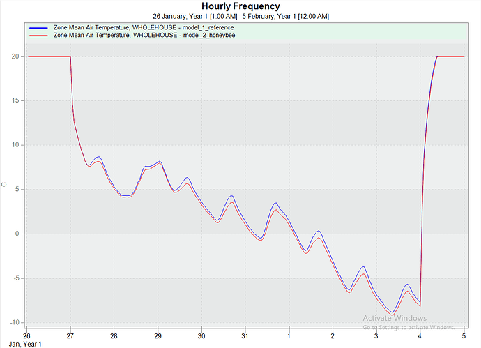
When I add the ‘Kiva’ solver from my ‘reference’ IDF into my Honeybee IDF file, I now get a result that looks like:

I still have a small 1/2 degree variation between the solutions, but it is much better aligned than previously.


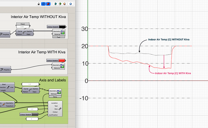
I have also replicated this result in Grasshopper in the attached example file, for anyone that is interested:

as shown; in my ‘power-outage’ scenario when Kiva is added to the honeybee IDF file, there is an enormous (~10 deg-C) drop in the air-temperature in the space relative to the ‘normal’ Honeybee solution in this case. I do not know if this an expected result or not, as I have not worked with Kiva before? But it does seem very significant, and it seems like perhaps having an option to use Kiva built into Honeybee would be a useful feature for the future?

example file:

kiva_testing.gh (95.1 KB)

@edpmay

2 Likes