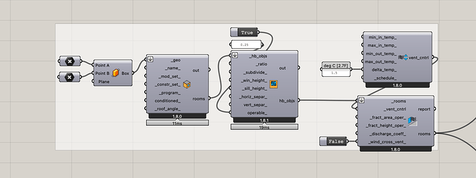
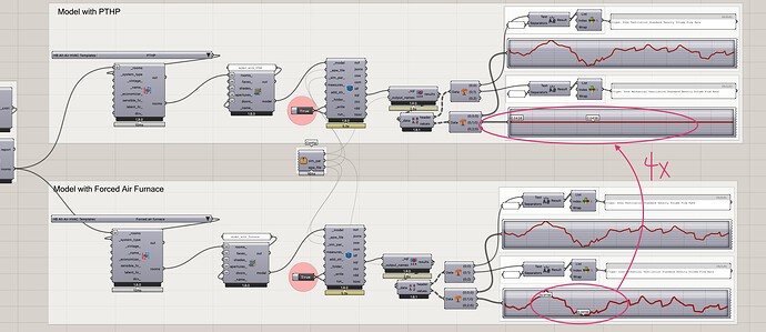
I checked your IDF: it seems that for the PTHP, the system considers autosize method for the OutdoorAir while for the All-air force Furnace, most of the OA system is empty and none.
The ventilation air flow you consider is for the natural ventilation of the windows. What your produced IDF shows the OA system specifically used for the HVAC is different.
for PTHP:
ZoneHVAC:PackagedTerminalHeatPump,
Room_3_dac48ee8 PTHP, !- Name
Always On Discrete, !- Availability Schedule Name
Room_3_dac48ee8 PTHP Inlet Air Node, !- Air Inlet Node Name
Room_3_dac48ee8 PTHP Outlet Air Node, !- Air Outlet Node Name
OutdoorAir:Mixer, !- Outdoor Air Mixer Object Type
Room_3_dac48ee8 PTHP OA Mixer, !- Outdoor Air Mixer Name
Autosize, !- Cooling Supply Air Flow Rate {m3/s}
Autosize, !- Heating Supply Air Flow Rate {m3/s}
Autosize, !- No Load Supply Air Flow Rate {m3/s}
Autosize, !- Cooling Outdoor Air Flow Rate {m3/s}
Autosize, !- Heating Outdoor Air Flow Rate {m3/s}
Autosize, !- No Load Outdoor Air Flow Rate {m3/s}
Fan:OnOff, !- Supply Air Fan Object Type
Room_3_dac48ee8 PTHP Fan, !- Supply Air Fan Name
Coil:Heating:DX:SingleSpeed, !- Heating Coil Object Type
Room_3_dac48ee8 PTHP Htg Coil, !- Heating Coil Name
0.001, !- Heating Convergence Tolerance {dimensionless}
Coil:Cooling:DX:SingleSpeed, !- Cooling Coil Object Type
Room_3_dac48ee8 PTHP Clg Coil, !- Cooling Coil Name
0.001, !- Cooling Convergence Tolerance {dimensionless}
Coil:Heating:Electric, !- Supplemental Heating Coil Object Type
Room_3_dac48ee8 PTHP Supplemental Htg Coil, !- Supplemental Heating Coil Name
Autosize, !- Maximum Supply Air Temperature from Supplemental Heater {C}
21, !- Maximum Outdoor Dry-Bulb Temperature for Supplemental Heater Operation {C}
DrawThrough, !- Fan Placement
Always On; !- Supply Air Fan Operating Mode Schedule Name
For the All air forced Furnace:
AirLoopHVAC:UnitarySystem,
Room_3_dac48ee8 Furnace Unitary System, !- Name
Load, !- Control Type
Room_3_dac48ee8, !- Controlling Zone or Thermostat Location
None, !- Dehumidification Control Type
Always On Discrete, !- Availability Schedule Name
Room_3_dac48ee8 Furnace Supply Inlet Node, !- Air Inlet Node Name
Room_3_dac48ee8 Furnace Unitary System Outlet Air Node, !- Air Outlet Node Name
Fan:OnOff, !- Supply Fan Object Type
Room_3_dac48ee8 Furnace Supply Fan, !- Supply Fan Name
BlowThrough, !- Fan Placement
Always Off Discrete, !- Supply Air Fan Operating Mode Schedule Name
Coil:Heating:Fuel, !- Heating Coil Object Type
Room_3_dac48ee8 Furnace Heating Coil, !- Heating Coil Name
1, !- DX Heating Coil Sizing Ratio
, !- Cooling Coil Object Type
, !- Cooling Coil Name
No, !- Use DOAS DX Cooling Coil
2, !- Minimum Supply Air Temperature {C}
SensibleOnlyLoadControl, !- Latent Load Control
, !- Supplemental Heating Coil Object Type
, !- Supplemental Heating Coil Name
None, !- Cooling Supply Air Flow Rate Method
, !- Cooling Supply Air Flow Rate {m3/s}
, !- Cooling Supply Air Flow Rate Per Floor Area {m3/s-m2}
, !- Cooling Fraction of Autosized Cooling Supply Air Flow Rate
, !- Cooling Supply Air Flow Rate Per Unit of Capacity {m3/s-W}
SupplyAirFlowRate, !- Heating Supply Air Flow Rate Method
Autosize, !- Heating Supply Air Flow Rate {m3/s}
, !- Heating Supply Air Flow Rate Per Floor Area {m3/s-m2}
, !- Heating Fraction of Autosized Heating Supply Air Flow Rate
, !- Heating Supply Air Flow Rate Per Unit of Capacity {m3/s-W}
None, !- No Load Supply Air Flow Rate Method
, !- No Load Supply Air Flow Rate {m3/s}
, !- No Load Supply Air Flow Rate Per Floor Area {m3/s-m2}
, !- No Load Fraction of Autosized Cooling Supply Air Flow Rate
, !- No Load Fraction of Autosized Heating Supply Air Flow Rate
, !- No Load Supply Air Flow Rate Per Unit of Capacity During Cooling Operation {m3/s-W}
, !- No Load Supply Air Flow Rate Per Unit of Capacity During Heating Operation {m3/s-W}
50.0000000000001, !- Maximum Supply Air Temperature {C}
21, !- Maximum Outdoor Dry-Bulb Temperature for Supplemental Heater Operation {C}
, !- Outdoor Dry-Bulb Temperature Sensor Node Name
0, !- Ancillary On-Cycle Electric Power {W}
0; !- Ancillary Off-Cycle Electric Power {W}

