Geometry manipulation in a custom dragonfly-to-honeybee script

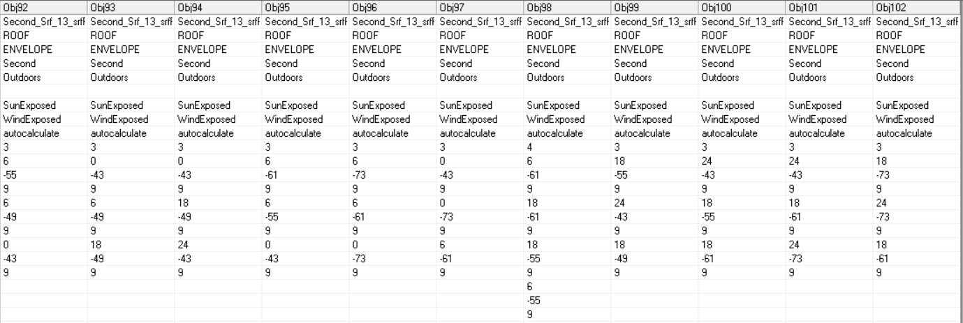
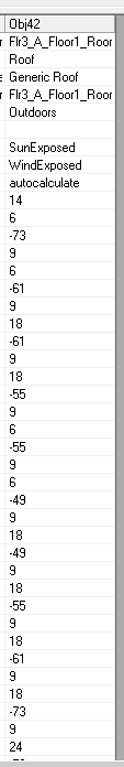
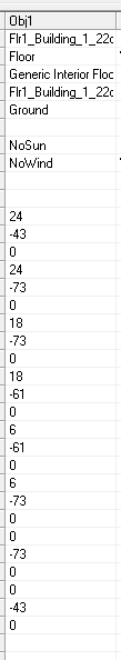
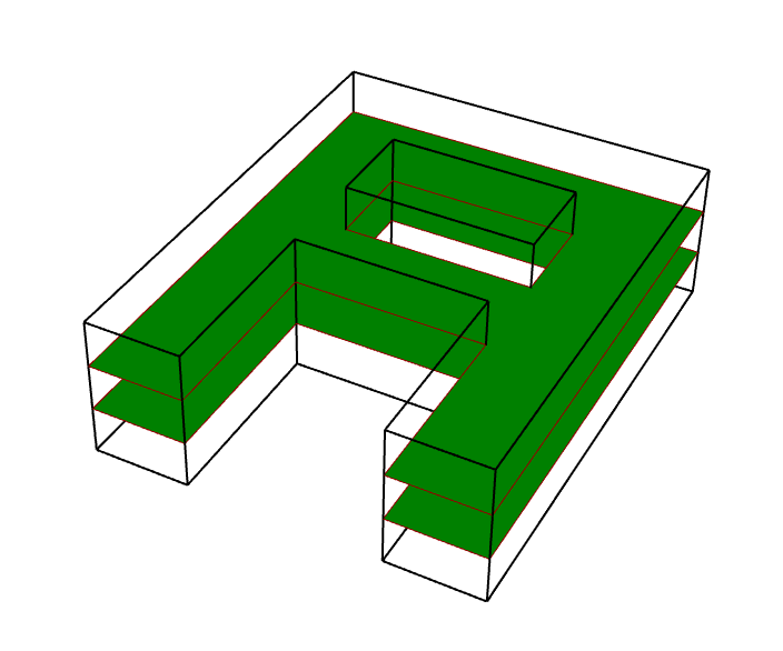
Hi @chris. I am sorry but I have another question. Taking into account the same geometries, Once I created the honeybee model and solved adjacencies between floors. How can I split the floors/ceilings into less complex geometries, such as rectangles? The output I am getting is the entire floor/ceiling surface and it can cause me problems with EnergyPlus. I think that in Honeybee legacy this process was performed automatically by the “SplitBuildingMass2Floors” component. I have seen that there are some possibilities in ladybug_geometry.geometry3d.face such as sub_faces_by_ratio_rectangle or sub_faces_by_ratio_sub_rectangle, but I am working with honeybee faces and I am struggling to get a solution to this.
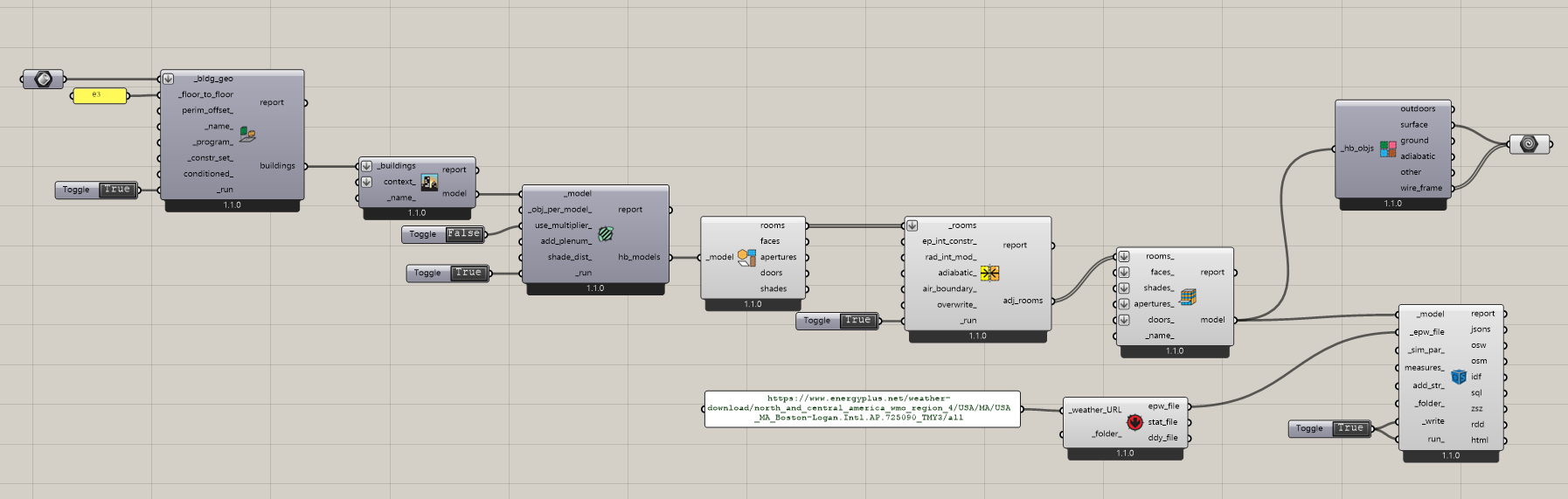
This is my code to create a honeybee model out of a solid moving from DragonFly to Honeybee:

# find min and max z coordinate of the building
min, max = geo_min_max_height(myBuilding)
# find the heights of each floor and the corresponding floor-to-floor height
floor_heights, interpreted_f2f = interpret_floor_height_subdivide(myFloorHeight, max, min)
# create the floors for the building massing
floor_breps = split_solid_to_floors(myBuilding, floor_heights)
floor_faces = []
for flr in floor_breps:
    story_faces = []
    for rm_face in flr:
        story_faces.extend(to_face3d(rm_face))
    floor_faces.append(story_faces)
# from the floors and floors heights create stories
dfBuilding = Building.from_all_story_geometry(myBuildingName, floor_faces, interpreted_f2f) # if I want to do core-perimeter zones I have to do it here
# convert DF model into HB model
hbModel = dfBuilding.to_honeybee(use_multiplier=False) # if it is True I get just one room, here I get one room for each floor
# get rooms from the entire HB model
rooms = hbModel.rooms
# solve adjacnency
adj_rooms = [room.duplicate() for room in rooms] # duplicate the initial objects
adj_info = Room.solve_adjacency(adj_rooms, tolerance)
# create model
finalModel = Model(myBuildingName, rooms = adj_rooms)

@fbattini,

I don’t understand what you are asking here:

Split floors/ceilings with what?
The legacy SplitBuildingMass2Floors component only did the operation that you are doing with your script there.

Hi @chris, thanks for your fast reply and for creating a new topic. Right now, I am moving from models I created with the legacy version to models created with the stable version by custom Python scripts.
I am having an issue for some models when I export them into EnergyPlus. When simulating, for some geometries I am getting the “vertex size mismatch” error between the touching floors/ceiling surfaces, even though the geometry is fine. This is an issue I didn’t have with the legacy version. I am using the exact same geometry from the same file to create the energy models.
As an example, I did it for an A shaped building as in this picture:


I had a look at the surfaces of the two models I got from this same geometry. I understood that the reason why I wasn’t getting an error for the model created with the legacy version is that, somehow, the touching floors/ceilings surfaces where automatically splitted into subsurfaces, while now I am having just one surface.
I attach a picture of the EnergyPlus surfaces for both cases, I report the roof surface but it is the same also for the floors/ceilings surfaces.
What I got from the legacy version:

What I got from the stable version:

I believe this is the reason why I am getting the “vertex size mismatch” error. For what I know, when a footprint has many vertices, as this one, it is better to split it into simpler surfaces. However, I also noted that from the stable version I got 14 vertices for the footprint, while they should be 12, maybe this is also causing me some troubles.
I tried to do it with the grasshopper components: the output surfaces I get have only 8 vertices, it is like it is not considering the hole of the letter, even though the visualisation is correct. But in this case the simulation runs.
Grasshopper workflow and visualisation:

I report one surface from EnergyPlus, it is the same for all the other floors/ceilings:

Thus, I would like to implement some lines of code in order to fix this issue, but I didn’t find a way to do so for now.
I hope now the issue is a bit more clear.
Thank you in advance for your help.
This is the geometry I used:
A.3dm (91.3 KB)
This is the grasshopper file:
A.gh (39.5 KB)

You are correct that the philosophy we took in Legacy was to just mesh any surface with holes, which would get the simulation to run but it makes the model really messy (giving you a bunch of triangles instead of a single clean surface) and it also interferes with the ability to map results from EnergyPlus back onto the original geometry. Lastly, it meant that you can never have a parent Face with both a hole and a child window (since the triangulation of the parent face essentially makes it impossible to assign a child window to it). However, I guess that this case is rare enough that we didn’t get complaints about it here on the forum.

In any case, for the new LBT plugin, we deal with holes by creating a single list of vertices that walks around the boundary of a shape and then turns inward to cut out the hole. This is why you end up with 2 extra vertices (14 instead of 12).

Your model simulated perfectly fine on my machine:

And it has your expected Surface boundary conditions:

Am I missing some error that you were experiencing here?

Thank you very much for the detailed explanation and for the time you are putting in this issue, I really appreciate that.

Ok, know I understand why I am getting 14 vertices in this case. Thanks.

If I run the simulation in that way it also works for me. Unfortunately, this is not what I want to do. What I am doing is to create the geometry only with LBT, export it as idf, customize each idf file with an external python code and then directly simulate it with EnergyPlus. This is how I create and export the idf file, I have these lines of code after those of my first post:

# convert honeybee to idf string
idfModel = model_to_idf(finalModel)
# write idf file
file = myBuildingName +".idf"
filePath = open(simulationFolder + file, "w")
for line in idfModel:
    filePath.write(line)
    filePath.close()

In this way I get an idf just with Material, WindowMaterial:Glazing, WindowMaterial:Gas, Construction, Construction:AirBoundary, Zone, BuildingSurface:Detailed, FenestrationSurface:Detailed. From this, I just keep the detailed surfaces and automatically set all the other properties according to my needs. In this file I have the 14 vertices for floors/ceilings/roof, as in the third pic of my last reply. If I run it, I get the “vertex size mismatch” error. I know it is a problem with this geometry because other models, with a different geometry, set in the same way, did not give me any error.

Now, even though the simulations with the component runs for me, I believe there is an error there. As in the last pic of my last reply, the floors/ceilings/roof surfaces have only 8 vertices. In fact, by checking the area of the these surfaces, it is simulating my geometry without taking into account the hole. As you can see from here, the roof area is equal to the area of the letter without the hole, so 576 instead of 504:

I am not sure, but it could be due to the code between lines 179-181 of the “HB Model to OSM” component , in which colinear vertices are removed.

# remove colinear vertices using the Model tolerance to avoid E+ tolerance issues
for room in _model.rooms:
    room.remove_colinear_vertices_envelope(_model.tolerance)

I don’t know if this is why, but there must be something happening there. So, for what I have seen the reason why the simulation is running properly is because it is not taking into account the hole in the geometry. Otherwise, I think it would give the same error I am experiencing.

I guess you are getting the right boundary conditions because you are displaying the surfaces before the run component, so they are not changed yet.

So, my idea to fix this was to split the floors/ceilings/roof into simpler surfaces by cutting them with vertical lines, in this case I would get 4 subsurfaces, but I hope it would work for every geometry. The thing is that I don’t know how to manipulate them because they are HB faces, so I cannot split them as usual with rhinocommon as here:

So, I was looking for a way to do it with LBT, if it is possible. As I said, I get this error for just some geometries, but I would really like to find a way to fix it in order to simulate everything.

Hi @fbattini ,

I ran the model_to_idf() method on my end with your geometry and imported the results to the OpenStudio App. From there, I could see that the hole is being correctly modeled in your example:

I get the same result using the “HB Model to OSM” component. And, now that I check it, I can see that the IDF actually has 12 vertices instead of 14 because, for this particular case, there are co-linear vertices that can be removed given the way that the seam for the hole meets the rest of the geometry.

But I think I know why you are getting the issue with 14 vertices that are mis-matched.

You can see that the model_to_idf method includes the removal of colinear vertices, to ensure adjacent surface vertices always match:


However, this process ONLY RUNS WHEN THE MODEL HAS A TOLERANCE ASSIGNED TO IT and I think, for your case, you have built a Rhino Model that has 0 tolerance, which basically indicates that you want to bypass all of the tolerance checks. So my suggestion is to make sure that you are assigning a non-zero tolerance to your honeybee Model before you translate it to IDF. Then, you should always have your geometry translated successfully, including all holes and no mismatched surface vertices.
2 Likes

@chris, you are THE BEST !

I knew there was something wrong in my code but I couldn’t find it! This is the row I edited by putting the tolerance value:

finalModel = Model(myBuildingName, rooms = adj_rooms, tolerance = 0.01)

Now I am having 12 vertices and the simulation runs successfully!
I don’t know how to thank you. Thank you so much.

3 Likes

@fbattini ,
You are welcome and it’s always good to have feedback about the SDK. I am sure that you are not the last person who will experience tolerance issues so I wanted to get your thoughts on some potentially better defaults that will help others avoid the situation you faced here.

If you look though the methods of the honeybee-core SDK, you’ll see that every method that requires a tolerance has it exposed as an input argument on the method. However, you will also see that, throughout honeybee-core, I use a default tolerance of 0.01 like you see here, which is “suitable for objects in meters” because, most of the time, these are the units of the geometry (or they are in Feet, for which 0.01 is also suitable). I know that this default is also approximately the tolerance of geometry in the OpenStudio SDK so it seemed appropriate for the majority of cases.

However, I also recommend that anyone creating new components using the Ladybug Tools SDK should pull the tolerance and angle tolerance values from the Rhino model in order to keep everything consistent. You can see that this is what I am doing here in the “HB Model” component by importing the model tolerances from the ladybug_rhino package and then I assign them to the Model object here:

This is also what I would recommend for your case, BTW, as long as you are running it within Rhino/Grasshopper and not in cPython.

The issue that I have been struggling with is, is it better to just put in a 0 tolerance as the default Model tolerance so that things will break and scripters will realize that they should pass in the tolerance from the CAD interface. Or is it better to just pick a default like 0.01, which has a higher chance of working for the majority of cases but may result in some weird behavior for some rarer cases. Given the number of people who have posted tolerance issues before and after I started using 0.01 as the default for certain honeybee-core methods, I am leaning towards the latter now. Also, the fact that I see you chose a default tolerance of 0.01 poked a hole in my original assumption that people will realize they need to pass the CAD interface tolerance when things break. So I think a change of defaults is in order.

But I guess there is one other possible option to consider for the model object because the Model has a property for units (either Meters, Feet, Inches, Centimeters, or Millimeters). So I could set the default Model tolerance to None and have it automatically computed based on whatever the units of the Model are when it’s initialized. So I would be something like:

  • Meters - 0.01
  • Feet - 0.01
  • Inches - 0.1
  • Centimeters - 1.0
  • Millimeters - 1.0

This will keep the tolerance consistently close to the OpenStudio SDK tolerance. Do you think this is a better default for the model instead of always setting it to 0.01?
Also, if anyone else has thoughts on this, please feel free to share them.

1 Like

Hi @chris. Thank you for asking my opinion about this. It is very interesting to get to understand the thoughts you put in the development of the SDK. Now, I completely get how you set the tolerances and I am more aware on how I should deal with them in the future. In fact, you are right here:

I decided to set it to 0.01 because I saw that you usually used that as default throughout the honeybee-core SDK and I thought that would work for me as well. Now that I am aware of it, I already change my code importing the model tolerance and I am using that. For my specific case it is the same, so I am still using 0.01, which is the tolerance of my Rhino model, which is in meters.

In my opinion, I think that would be a very good solution. It would be more flexible for sure. It would also help who is not so familiar with coding or with the LBT tools SDK in general to avoid tolerance issues along the way.

Thank you for the response, @fbattini . I incorporated your comments into this PR that I just merged into the codebase:

Now, the default tolerance will be set based on the units.

1 Like