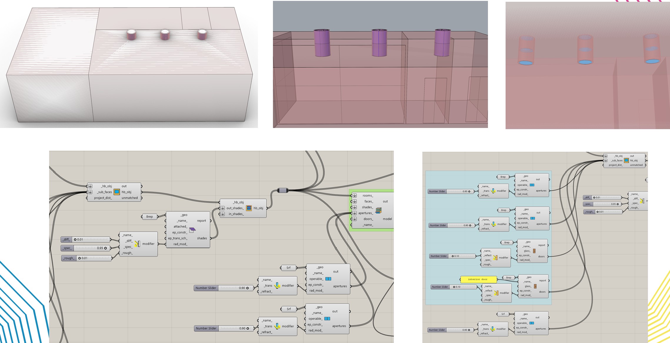
I want to design three solar light tubes installed in the ceiling, as shown in the image. The tube section also extends down into the building (the purple-colored part) and is made of a highly reflective material. Both the top and bottom ends of the tube are made of high-transmittance glass. The connection point between the tube and the roof is also an opening (a hole).
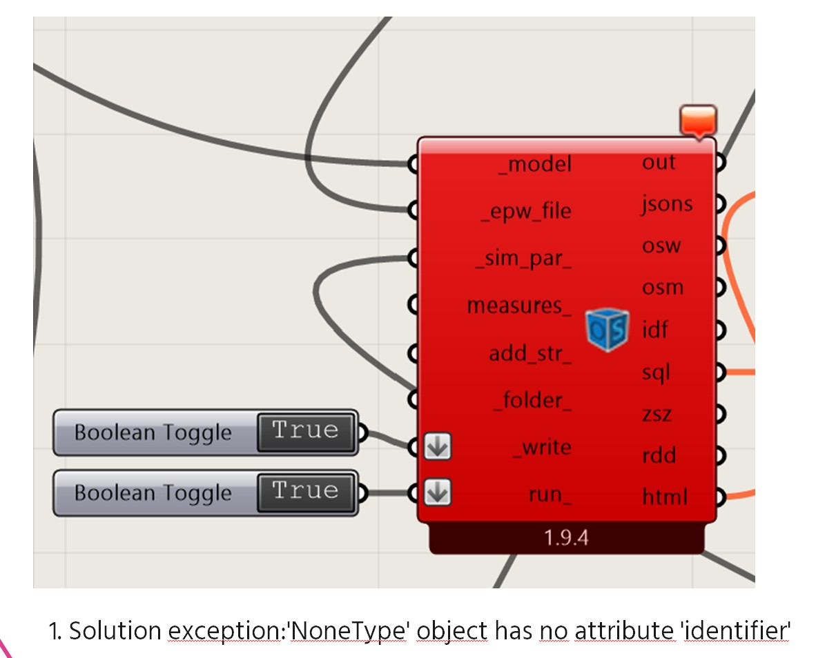
However, Honeybee requires closed solids, so I cannot create an actual void. For this reason, I modeled this part as if there were glass there as well. I defined the reflective tube part as a shade. I also connected the glass at the top and bottom directly to the HB model. Honeybee Radiance accepted these glass elements even though they were not previously mentioned in the program, but the Honeybee Energy part does not accept them. How should I define these glass elements? The image below shows the error in Honeybee Energy.
I also tried another method. I created the solar light tube as a room. I defined an air boundary between it and the space it connects to, which created a void. I assigned a reflective material to the room’s exterior wall, and since it was a room, I was also able to place windows at the top and bottom. The Honeybee Radiance part worked successfully, but the Honeybee Energy part could not complete the calculation even after a very long time, and I was not able to open the file again afterward. This method turned out to be unsuccessful.
I couldn’t achieve the desired results with either method
When designing a solar light tube, how should I define
-
the tube part,
-
the glass part, and
-
the void part?
I would be very happy if you could help. Thanks