I have a question about the impact of the shape of a building on natural ventilation and its effect on indoor thermal comfort.
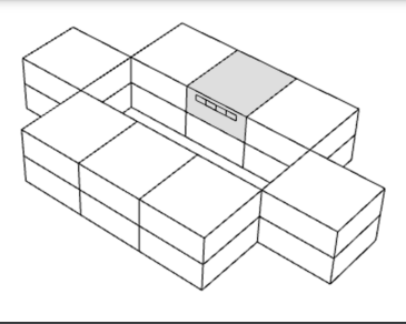
For example, my goal is to know the thermal comfort inside a naturally ventilated room that overlooks an interior courtyard (see model below).
The room is modeled as a room, while the rest of the building is modeled as a shade.
I would like to know, when I simulate this naturally ventilated room to achieve thermal comfort according to the ATC, is the effect of the shape of the courtyard building on the ventilation taken into account in the simulation?
In other words, is the impact of the building shape attributed to the context (shade) on the outside winds and the resulting pressure on the facades considered on the effectiveness of natural ventilation in the room?
No, only the orientation of the window in relation to the direction of the winds at the hour is used to determine wind-driven pressure. Any obstructions between the window and the rest of the exterior environment will not affect the wind-driven flow through the window. This is true for both the default simple air flow objects and the detailed air flow with the AFN.
If you badly needed to account for this, you would have to run several time-intensive CFD simulations to determine hourly pressure coefficients that you then feed to the Ventilation Opening objects using an OpenStudio Measure or OpenStudio SDK inside a GHPython component.
But usually this is all overkill and you are better off spending your time on trying to get the airflow through the interior and the controls for the window openings as close to reality as you can before taking on this big effort of modeling exterior obstructions may diminish the wind speed at the window.
I’ll add to Chris’s comment that the current HB implementation of the AFN computes surface wind pressure coefficients based on a simplification of the input geometry as an oriented rectangular prism.
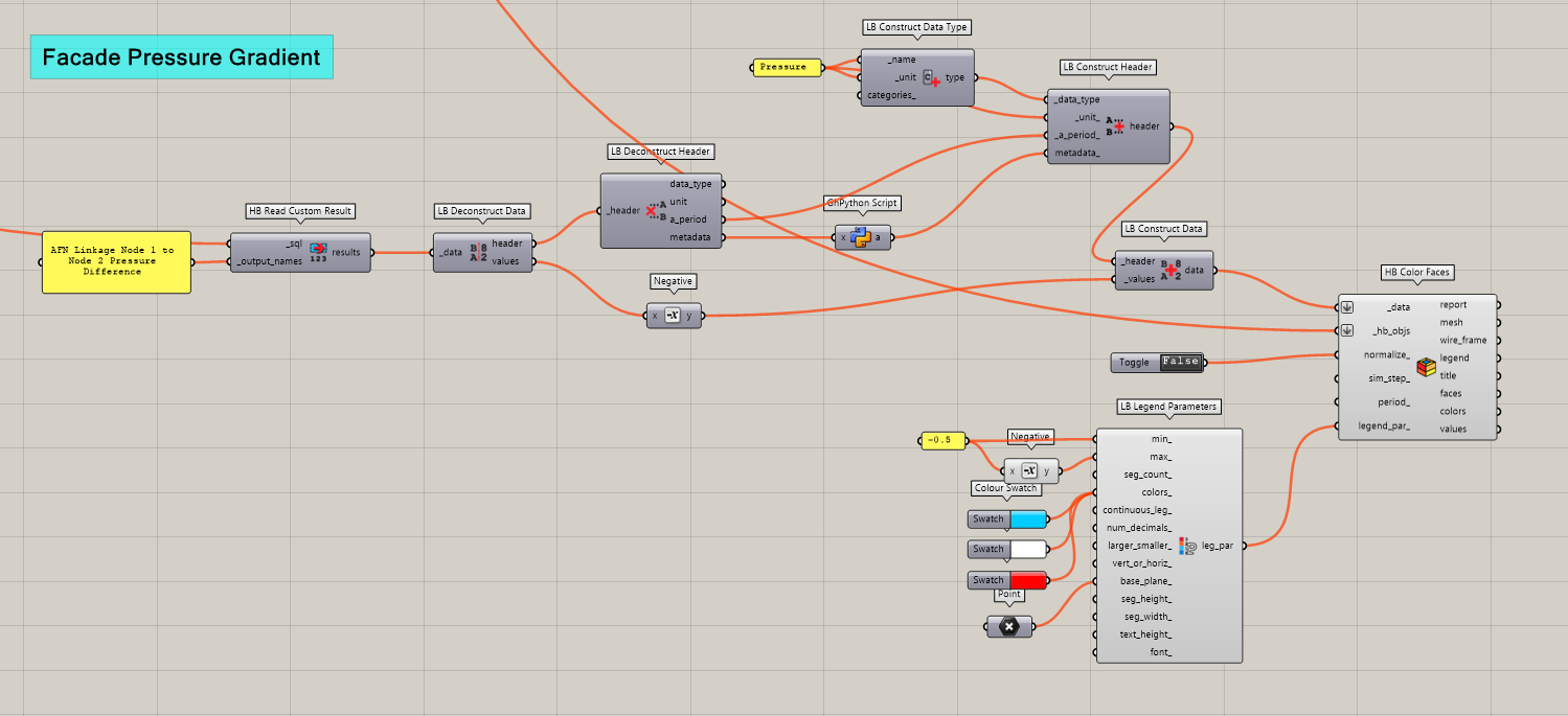
You can visualized this by mapping the custom EP output AFN Linkage Node 1 to Node 2 Pressure Difference to colored surfaces. I do this with the following custom GH script, which reads the output into the HB Color Faces component.
The AFN linkage nodes refer to the locations in the model that simulate the air pressure network, which includes locations within the HVAC system, as well as surfaces. Since the HB implementation only places them on the surfaces, you can safely change the header data from System to Surface which permits it to work with the HB Color Faces component. I do this with the following custom ghpython script:
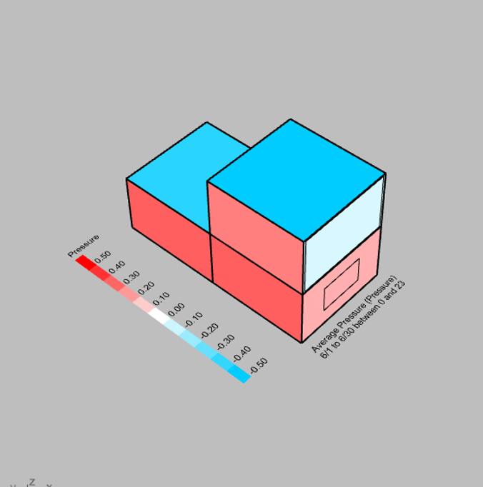
In this case, since the building is essentially rectangular, the wind pressure difference aligns with our expectations, with each orientation having a different wind pressure difference. This analysis is for a certain period in Philadelphia where the winds are coming from the south west direction, explaining high positive pressure delta on that orientation, and the negative pressure difference at higher levels to reflecting exfiltration due to the the stack effect. With more complex geometries, you’ll see that the wind pressures will still follow the four orientations of an oriented rectangle, which will give you some idea if the simplification is reasonable or not.
Hey, since I am also working on the effect of different courtyard properties on natural ventilation and indoor thermal comfort, I was wondering if you’ve found a precise way to evaluate this.