Ideal Air Loads - separate space conditioning and ventilation heat/cool energy

Hi All
We using ideal air loads at the early stages of projects very regularly. However, as far as I can see from the documentation, ideal air loads will not allow the space conditioning to be separated from the ventilation heating/cooling, since it’s a VAV type approach. This is problematic in the UK as we almost always have DOAS system and need to separate them for proper equipment sizing.

Right now, our workaround is to set the fresh air requirements to zero for all rooms, which gives a good estimation of the space conditioning requirement (with the assumption that the mech vent has a neutral impact on the heat/cooling, which is acceptable for our Mech. Engineers). We then calculate the fresh air heating/cooling separately using a hand calc, “mCpDeltaT” style… This is at least understandable from out point of view, but we know it’s not as accurate as we’d like.

Maybe we’re missing something with the Ideal Air Loads component – or maybe it’s missing something?

How can we break out the heating and cooling for the space conditioning separately from the air conditioning?

Hope that makes sense!?

Will

1 Like

Hey @wallen ,

This is correct in principle:

You are correct that the Ideal Air system is an All-Air system (like VAV) so it does both conditioning of ventilation air and management of space loads with the same air stream. This means that the cooling and heating values that you get in LBT-Grasshoppper when you simulate an Ideal Air System have both the ventilation load and the space load grouped into the same data.

However, because the Ideal Air System is simply telling you the thermal energy to be added/removed from the room + the ventilation air, getting these two thermal loads as separate terms out of EnergyPlus is pretty straightforward. It’s not like you are modeling a detailed VAV system and you are trying to disentangle which electricity or fuel was used for ventilation vs. space load (very difficult).

If you want to get separate values for the ideal load applied to the space vs the ideal load applied to the ventilation air, you do not need to run two separate simulations of energyplus (one with ventilation and one without). Nor do you need to approximate ventilation load with mCpDeltaT, which can miss the latent load and doesn’t let you account for things like heat recovery or economizers easily.

Instead, you can do it by just requesting EnergyPlus output variables that don’t lump the ideal air ventilation load together with the ideal air space load. If you look at the .rdd file that you get whenever you simulate a model with ideal air systems in it, you’ll see that there are a bunch of Ideal Air outputs to choose from:

The “Supply Air” outputs at the top are what they LBT-Grasshopper components parse in order to import the cooling and heating loads. So these account for all parts of the ideal air system all together (including space loads, outdoor air loads and heat recovery). After these outputs, you will see that you have “Zone” outputs, “Outdoor Air” outputs, and “Heat Recovery” outputs. The “Zone” outputs give you the space loads without accounting for any ventilation air and the other two together give you the ventilation load.

If you are just looking to get the space/zone load separate from the ventilation loads (accounting for both outdoor air and heat recovery), this is the simplest way to do it:

separate_ideal_air_vent_and_space_load.gh (61.6 KB)

Granted, you will see that the ventilation load can go negative unlike the space load:

This is to be expected since, sometimes, the temperature of the outdoor air helps you heat or cool the space when you need it. Like when your room has a cooling load but the outdoor air is below room temperature. In this case, the introduction of outdoor air actually prevents you from needing to run the cooling coil to meet 100% of the space cooling load.

If this nuance of the ventilation load isn’t something that you want for your loads study, then you can just use the LB Apply Conditional Statement component to remove the hours with a negative load. But it’s an important thing to consider, particularly if the DOAS on your real building has an air-side economizer feature on it.

I hope that helps.

3 Likes

Hi Chris,

That’s really helpful. I think we’ll be able to get what we need through using those output variables. However, I think that what we are looking for is slightly different to what you show in your example file.

With my ‘MEP engineer’ hat on, I want to know two things;

  1. The room space conditioning load, which might be dealt with by a fan coil unit fed by an ASHP. This is the “Zone” outputs you refer to. Easy! I can size my ASHP with this.
  2. The energy required to condition the incoming fresh air. This would be the energy required by the coils in the Air Handling Units (ignoring losses). I would use this to size a different ASHP, dedicated for ventilation maybe. However, I believe that the example provides the load that the fresh air introduces into the space, which is different.

Is it possible to acquire the energy needed to temper the fresh air? I presume we would need to set the limits on air temperature supply, since a fresh air DOAS might only supple between 18 and 24?

I think the ‘Zone Ideal Loads Outdoor Air Total Cooling Energy’ is what we want, for cooling?

Thanks for helping with this, it’s baffled us for a while now.

Hey @wallen ,

I didn’t realize that you were trying to use these loads to size HVAC equipment. If that is the case, then running an annual simulation of ideal air loads really isn’t the best way to do this with Honeybee. This is because engineers typically don’t run annual simulations to size equipment and instead run simulations of summer and winter design days for this purpose. Granted, there are some edge-case exceptions where an engineer might run an annual simulation to size HVAC equipment like heat recovery chillers, where the size is dictated by the maximum simultaneous heating and cooling across the building. But something like an ASHP is almost always going to be sized based on a winter design day where all internal loads discounted and solar load is set to zero. Oftentimes, this is a little more extreme than what you’ll find in an annual simulation, where a space might be occupied every day and even cloudy days still give you a little solar energy. But the thought is that, even if no one is in the space or someone constructs a building across the street or plants a tree that blocks all solar load, the heating system will still meet the setpoint.

Normally, the workflow that I would recommend for this type of sizing study is to pick a template HVAC system that reflects the HVAC equipment you are planning to use (eg. DOAS with fan coil chiller with central air source heat pump for your case). Then you would use the HB Read HVAC Sizing component to read in the sizes of equipment like the ASHP. These sizes are determined by running a simulation of design days with E+ before any annual simulation is started and so they align with the criteria used by MEP engineers.

Now, I know that the template DOAS with fan coil chiller with central air source heat pump uses a single ASHP to supply hot water to both the ventilation heating coil and the space heating coils, which I realize is not the HVAC architecture you are trying to size here. You could use Ironbug set up the system exactly as you want it with separate plant loops for ventilation vs. space loads (maybe using district heating/cooling objects instead of an ASHP because you mainly care about the thermal load of hot/chilled water you need to produce with the ASHP rather than the electricity consumed by the ASHP).

If you want, I can set up an example file for this workflow with Ironbug, which is the “best practice” way to do this type of sizing. Or, if you want to press forward by heavily postprocessing the Ideal Air outputs, this is also a way to do it, albeit with more assumptions than you might have to make when modeling the full HVAC system where the DOAS supply temperature and the hot/chilled water temperatures match what you actually plan to use on the building. Regardless of the method you choose, I would recommend using the HB Simulation Control component to ensure that you only run the simulation for the design day “sizing period” and not the annual “run period.”

Also, for pressing forward with ideal air, this isn’t entirely correct:

The example I provided is showing the load that the fresh ventilation air is providing to the ideal air supply air (after that fresh ventilation air has passed through heat recovery if it exists). The ideal air supply air takes the sum of this fresh ventilation air load along with the zone load needed to meet the thermostat setpoint and runs either a heating or cooling “coil” to make up the difference before introducing the supply air to the room. This “coil” load of the ideal air system is what is reflected in the E+ “Supply Air” outputs for ideal loads.

If your ventilation system does not have heat recovery, then using the ‘Zone Ideal Loads Outdoor Air Total Cooling Energy’ is an acceptable way of getting to the ventilation load that you want. This is because it’s effectively the same as subtracting the Zone load from the Supply Air load for this case but without the negative values for hours where the ventilation air reduces the overall need to run the heating/cooling coils. If your ventilation system has heat recovery, then you will need to do additional math with both the “Outdoor Air” load and the “Heat Recovery” load to get the actual size of a coil that you might put into a DOAS air loop.

I hope that makes things clearer.

2 Likes

Hi Chris,

Sorry, I should have probably taken more care with the last answer.

We are working on a masterplan, with around 12 buildings, mixed use and some labs, and looking to understand the general demand across the site, to assess the potential for an ambient loop and also to understand to what extent the energy systems will be centralised. For this purpose, I think we need to run the annual simulation to find the simultaneous heating and cooling and see the typical energy flows.

If I understand correctly, then we need to Subtract the Heat Recovery from the Outdoor Air to get the load at the AHU coil?

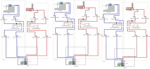
This is the approach that was recommended by a mechanical engineer to me a while ago, to set up a district heating and a district cooling system for each thermal zone (or zone groups, depending on the model granularity), it makes things easier compared to nitpicking Ideal Air System results.

Example setup in DesignBuilder:

I would be curious to see a similar setup, I haven’t tried this in Ironbug before.

Thanks for clarifying, @wallen .

It seems that you are modeling one of those “edge-case exceptions where an engineer might run an annual simulation to size HVAC equipment.”

You are right that the size of this ambient loop is driven by the peak simultaneous heating and cooling across your masterplan buildings, which requires an annual simulation rather than a design day.

I believe this is correct, though it’s always good to run a test and make sure that the result makes sense.

I am confident that the ventilation load you are trying to get is equal to the Supply Air Load minus the Zone Load with all of the negative hours set to zero. Another way of arriving at this same timeseries data set should be to subtract the Heat Recovery Load from the Outdoor Air load. So that is the test I would run to be sure.

Now that I know that this isn’t relevant to @wallen 's question, I would suggest opening a separate topic for it, @furtonb. It would also be good to get clarification whether it’s the two separate plant loops in ironbug that you want to have an example for or whether you just want to know how to extract the sizes of HVAC equipment using the HB Read HVAC Sizing component. For the latter, I would point you towards this tutorial video:

1 Like