I am wondering what is the default setup for mechanical ventilation when using the Ideal Loads Air System in HB (how is the outdoor air flow rate calculated?).
The .idf contains the following:
DesignSpecification:OutdoorAir, ** zone_1OutdoorAirCntrl, !- Name** ** Sum, !- Outdoor Air Method** ** 0.0, !- Outdoor Air Flow per Person {m3/s-person} 0.0, !- Outdoor Air Flow per Zone Floor Area {m3/s-m2} , !- Outdoor Air Flow per Zone {m3/s} , !- Outdoor Air Flow Air Changes per Hour {1/hr} ; !- Outdoor Air Flow Rate Fraction Schedule Name**
Which made me think there was no outdoor air flow. But I guess I am wrong !
I’m ok with the meaning of ‘Sum’ value. So you confirm that default setup for mechanical ventilation is ‘no mechanical ventilation’ when using the Ideal Lodas Air System in HB ? (Outdoor Air Flow per Person = 0 AND Outdoor Air Flow per Zone Floor Area = 0).
I still have doubts, because when adding “Zone sensible Heating Rate” as output, I get non-null results. (I thought “Zone Sensible Heating Rate” was directly related to the Outdoor Air Flow)
The default is not 0. It is set by the zone program. Use the readMe! Output of the “Set Zone Loads” component to see your Jones’s ventilation specifications.
Sensible heating is pretty much the same as normal heating in an ideal air loads system. It’s dependent on ventilation as well as everything else.
Hi Chris,
I have one similar question.
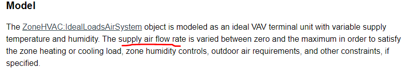
As defined by EnergyPlus, the ideal loads air system changes the supplied air flow rate to satisfy the heating and cooling loads.
But, at the same time, with the ‘set zone loads’ component, I set the ventilation rate per area and per occupant.
I wonder which value is used as the final air flow rate for the zone? The one that I set in ‘set zone loads’ or the one that the system calculated by itself for the heating and cooling loads?
From my reading of the (somewhat unclear) EP Engineering Reference on the topic[1], the supply air flow rate for the zone is conditionally determined based on a couple of factors.
The specified ventilation air (calculated according to the formula in the previous post) is your minimum flow rate. It’s then increased to match the maximum flow rate from the following three calculations:
The air flow rate required to meet the zone sensible load at the maximum/minimum supply temperature limit.
The air flow rate required to meet the dehumidification load as defined by a humidistat at your minimum supply humidity limit (if this is set).
The air flow rate required to meet the humidification load as defined by a humidistat at your maximum supply humidity limit (if this is set).
So for example, let’s say your air flow rate to meet the zone sensible load at Tmax is your max flow rate, then your supply air mass flow rate (ms) is:
ms = (Qz / Cp * (Ts - Tz))
where:
ms = Zone air flow rate (kg/s)
Qz = Heat transfer in zone
Cp = Specific heat capacity of air
Ts  = Supply temperature limit (Tmax or Tmin for heating/cooling respectively)
Tz = Zone air temperature
But if you have no heating or cooling loads, then it’ll be your ventilation air flow rate. After the flow rate is calculated, EP calculates the sensible/latent heat recovery that occurs at your mixed air box, and then, finally, your zone heating/cooling coils will supply the remaining heating/cooling energy to meet your zone loads.
Dear Saeran,
Thanks for your explanations,
Could you please help me with the below questions
so Ideal air load is a HVAC system? (As it is one of the HVAC option in grasshopper-Honeybee)
If we have a fixed window, does it make sense to say Ideal air load is better choice for considering for small office building?
No, the Ideal Loads Air System is not a real HVAC system. It’s modeling a theoretical HVAC air system that would meet the zone heating and cooling loads exactly (or “ideally”). So rather then calculate the actual electrical or gas energy for zone loads, like you would for real HVAC systems, and the various efficiencies gained by using different equipements, the Ideal Loads will just calculate the thermal energy required to fufill the zone thermal energy demand. This is useful in scenarios where we want to understand just the thermal energy breakdown of a zone, which is why it’s used for the heat balance and peak load studies, or early stage design when HVAC hasn’t been specified yet.
For that reason you can’t say an Ideal Air Load is a better or worse choice from an actual HVAC system, you’ll have to select a real HVAC system instead.
Hi @SaeranVasanthakumar,
I have a question about this Ideal Airloads definition.
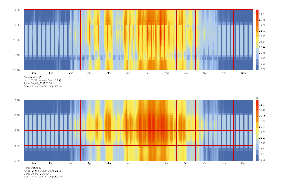
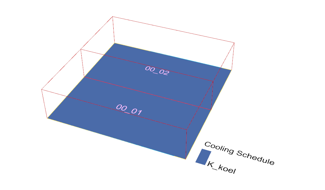
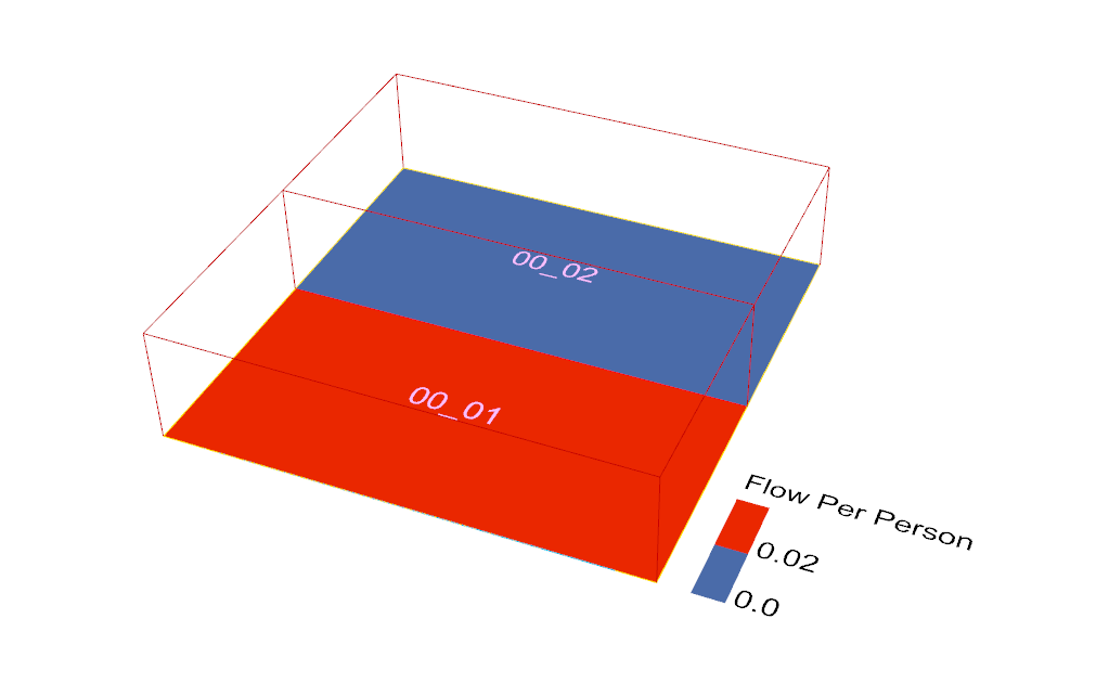
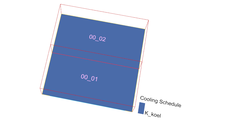
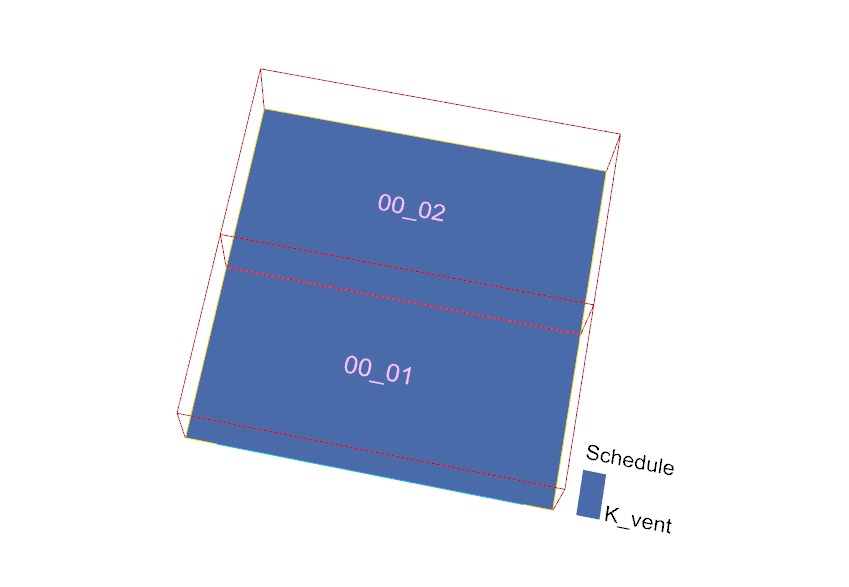
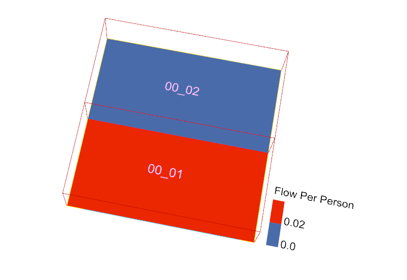
With a small building simulation with Ideal Airloads I ran into the following problem. For one room the ventilation is set to 0 for the other a value of 0.02 [m3/s.p]. For both rooms the same cooling setpoint schedule is used. In the room with ventilation room setpoints are met, but in the room without ventilation no cooling is taking place. So cooling loads are not met.
Hmm, I’m a little busy right now so can’t look into this in detail, however, my initial impression is that this doesn’t seem to have anything to do with the ideal loads system as I understand it. Even if there’s 0% outdoor air, the ideal loads system should still condition the return air, so I see no reason why the cooling load isn’t working in this case.
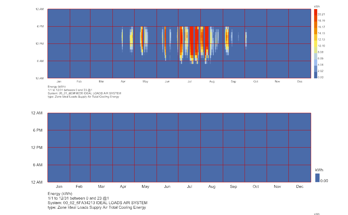
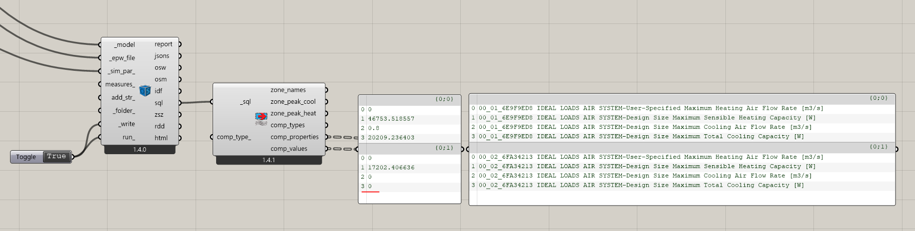
What you have going on there seems to be unrelated to the ventilation specification. Clearly you still have the ideal air system heating the space that has no mechanical ventilation. So it’s not like the ideal air system can’t recirculate the air of the room when there’s no outdoor air. Rather, it seems that one of your rooms has the ideal air cooling capacity sized to zero:
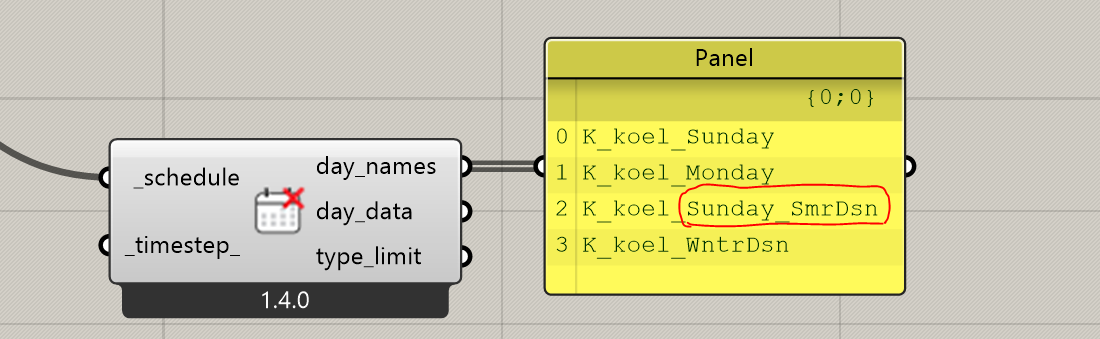
Thanks for pointing this out. I checked the model and indeed the summer design day schedule was different from what i had imagined. This one caused the problem:
summer_des: An optional list of 24 values that represent the schedule
values at each hour of the summer design day. This can also be a
single constant value for the whole day. > If None, the daily > schedule with the highest average value will be used.
With cooling setpoints the wrong schedule will be used.
But one thing surprised me. Because for both rooms the same cooling set point schedule is used you would expect in both rooms cooling demand is not met.
I think that part is because the ideal loads system doesn’t use its system capacities when the computing the required heating/cooling energy. The system cooling capacity seems only to be used to define the upper limit of the supply air flow rate (via the system maximum cooling flow rate).
According to the Engineering Reference[1]:
If outdoor air flow rate exceeds applicable maximum flow rate (heating or cooling) then reduce outdoor air mass flow rate, issue warning, and set supply air mass flow rate equal to outdoor air mass flow rate
Once the supply air flow rate is set (in this case, to your ventilation flow rate), the supply temperature is simply calculated to offset the zone energy demand using the heat equation:
T_s = T_z + \frac{\dot{Q}_z}{C_p \dot{m}_s}
So, it appears you can have a system sized to zero, but the ideal loads system will still maintain your temperature setpoints by conditioning the outdoor air specified by your ventilation requirements.
Thanks @SaeranVasanthakumar for the clarifiction.
It keeps being a complicate concept, using “theoretical” air to meet heating and cooling loads. Never understood why Eplus choose for this method. It makes things unnecessary complex.
Yep, that’s definitely it, @Erikbeeren . You can see here that we changed this default behavior in the latest development version of the plugin because people found it counter-intuitive for setpoints:
So this is much less likely to happen if you use the latest development version of the plugin.
 Sorry for my late reply.