I am trying to compare simulations models prepared in Grasshopper and Rhino. Both my models have overcast sky (in Honeybee using CIE uniform sky). However, I am getting a huge difference between the values of two simulation models. With Honeybee it is higher and almost 2.5 times of Dialux simulation. For your information, I have tried to keep the materials properties for both models same. Please find the gh file together with grid values for the simulation. Could please tell me if there is anything I am doing wrong in the gh file or not? also, if anyone also has experience in DIAlux can you comment on my result images?
@kmhalam
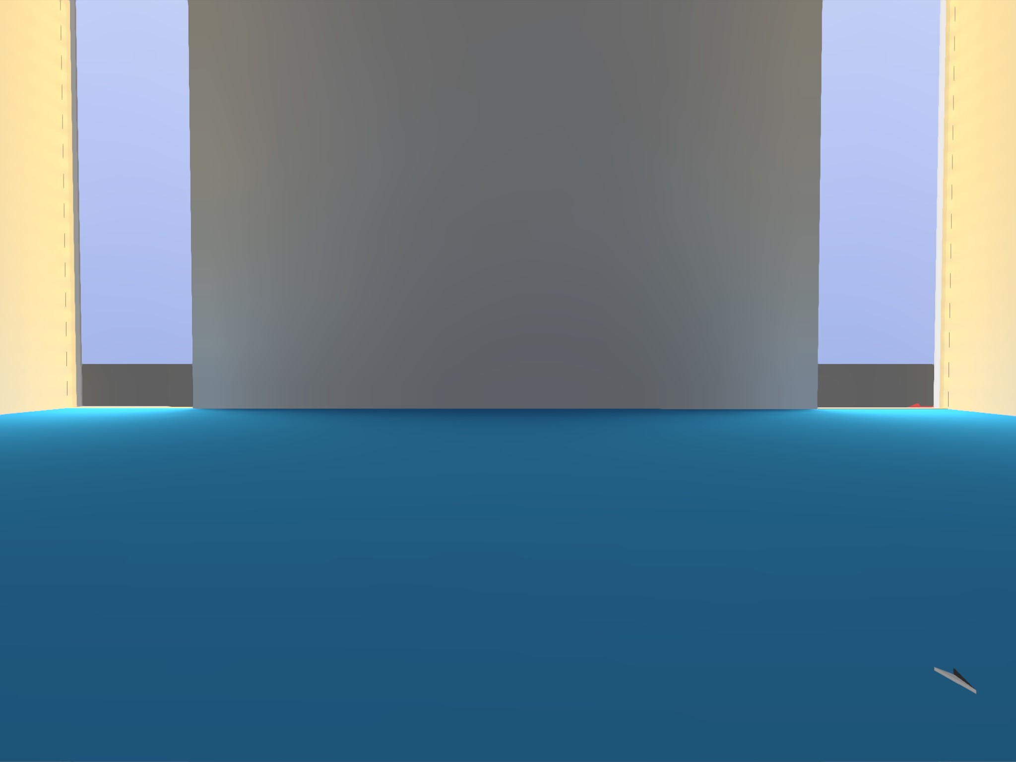
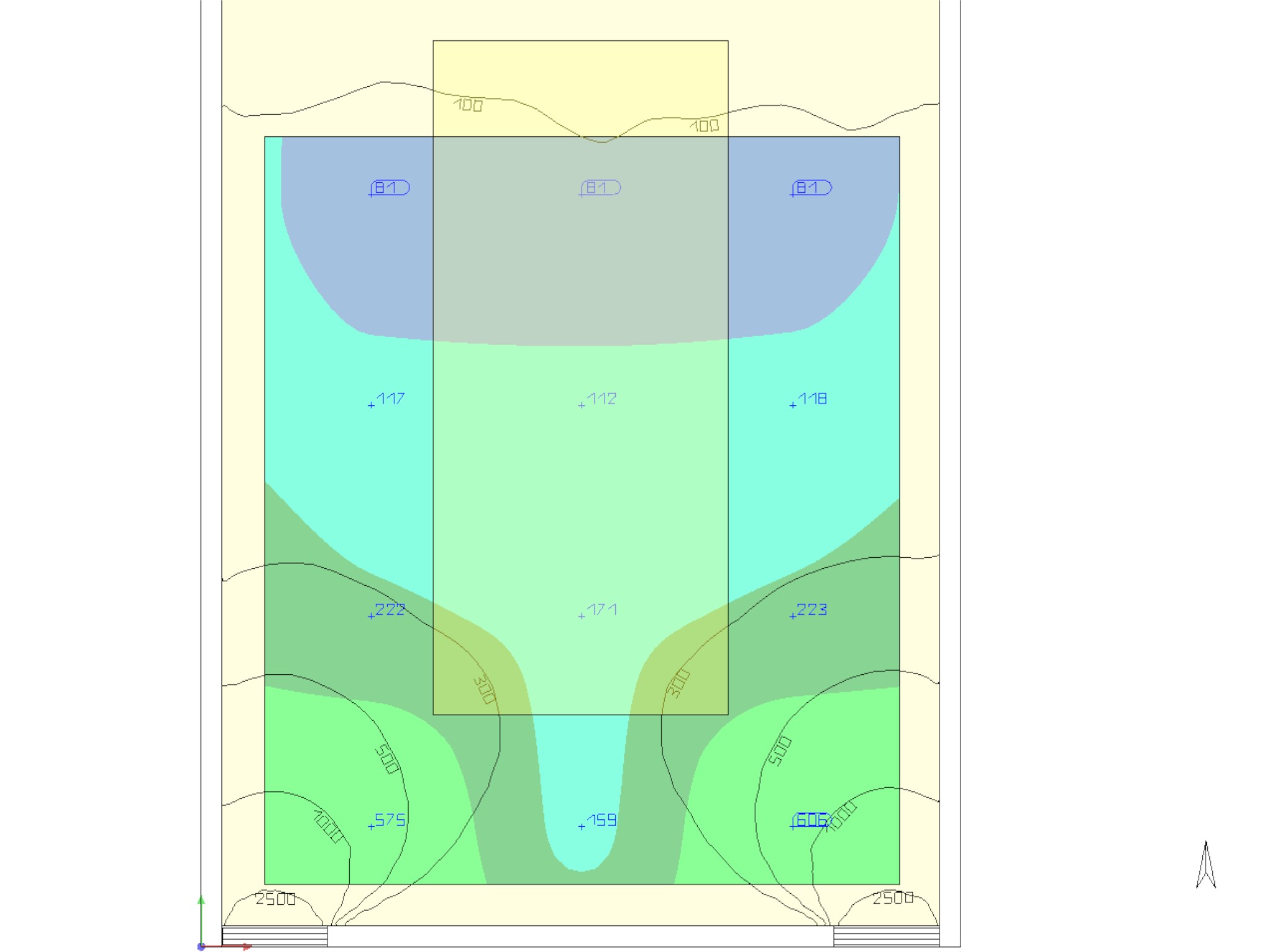
First up, can you try the simulation with just the ground plane first and see if you get the same values of illuminance on the ground for Honeybee and Dialux. If that matches to the same illuminance value, then it makes sense to compare the models.
If you do get same or similar values, then I would suggest setting the “accurate” setting in Dialux and setting -aa 0.05 in Honeybee settings for the simulation. Its been at least 7 years since I last worked with Dialux, however, I dont think much has changed with the calculation engine… they appear to have the evo interface now.
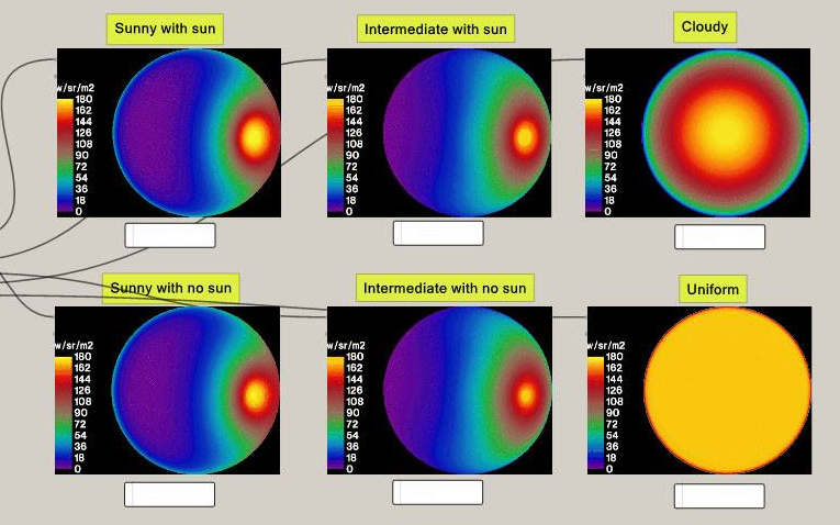
Why not using overcast/cloudy sky? Uniform sky is different from overcast (image below) which might be the source of the error. As @sarith mentioned for comparing the results you need to first ensure skies are the same in both studies.
Yup, this would be the first thing to fix. If you are still getting errors, it might be worthwhile to turn both the rooms completely black and repeat the calculation with a measurement location close to the window.
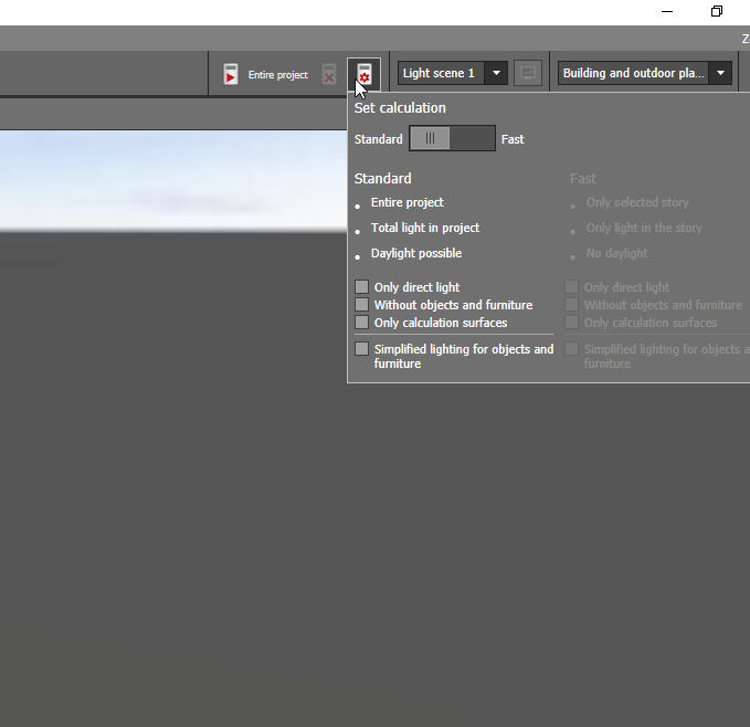
The “problem” with Dialux is that there are very few options for the user to set. Radiosity, the calculation, method employed in Dialux employs meshing to subdivide geometry into smaller surfaces. The accuracy of results will be proportional to the resolution of the mesh. In a tool like AGI32, this can either be controlled directly by specifying the mesh level or by letting the computer do it for you via adaptive-subdivision. Here is a short video that explains this.
With Dialux, one only has two simplistic options: standard and fast (whatever they mean!).
These options work well if one is doing electric lighting simulations but arent really helpful to comprehend the calculation method for daylighting simulations.
If you are serious about doing daylighting calculations with Radiosity-based tools Relux or Licaso would be better options. Relux has a Radiance-backend that has been around for several years and Licaso, a fairly recent tool, was benchmarked against Daysim.
The idea with the black room should work becuase then you do away with ambient calculations completely.
and for more specific answer to your question see this:
and one more item to think about is what does Dialux does for ground reflection calculation? gensky has this value built in unless you overwrite it using -g option. See the first link to gensky manual.
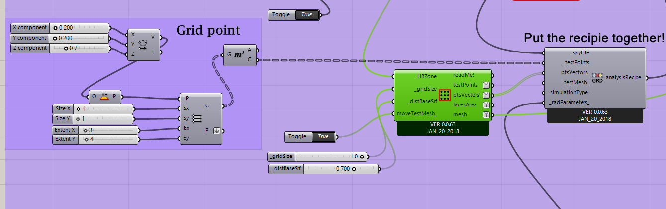
I have one specific question related to the grid arrangements. I am not using the test points in Honeybee_Generate Zone Test Points component for my model. Instead I have plugged in grid points like the following screenshot:
Does that mean if I replace the actual HBZone floor surface with the desired grid surface would fix the mesh patch? Or do I also have to work on the create mesh function?
HB is using GH meshing commands (under the hood). The grid point are the center point of the patches.
You are trying to create a personalized grid. You need that the patches fit the grid points. You don’t need to replace the HBZone surface, but you need to be consistent connecting the"other" surface.
I will recommend you to search in the forum for “Uniform grid”. You’ll find there something close to what you want (assuming that i understood well).
-A.
Sorry, its a little confusing for me. GH meshing is not my expertise. It would be great if you could elaborate.
Inside the component — the testSurfaces are retrieved from HBZone (see the function below)! And according to you I have to match mesh patches with the personalized grid. My idea was to replace this testSurfaces with the personalized grid surface
def getHBZoneFloorSurfaces(HBZone):
try:
# call the objects from the lib
hb_hive = sc.sticky"honeybee_Hive"
HBZone = hb_hive.callFromHoneybeeHive([HBZone])[0]
    for HBS in HBZone.surfaces:
        if int(HBS.type) == 2:
           testSrf = copy.deepcopy(HBS.geometry)
           testSrf.Flip()
           testSurfaces.append(testSrf)
    return testSurfaces
except:
    return -1
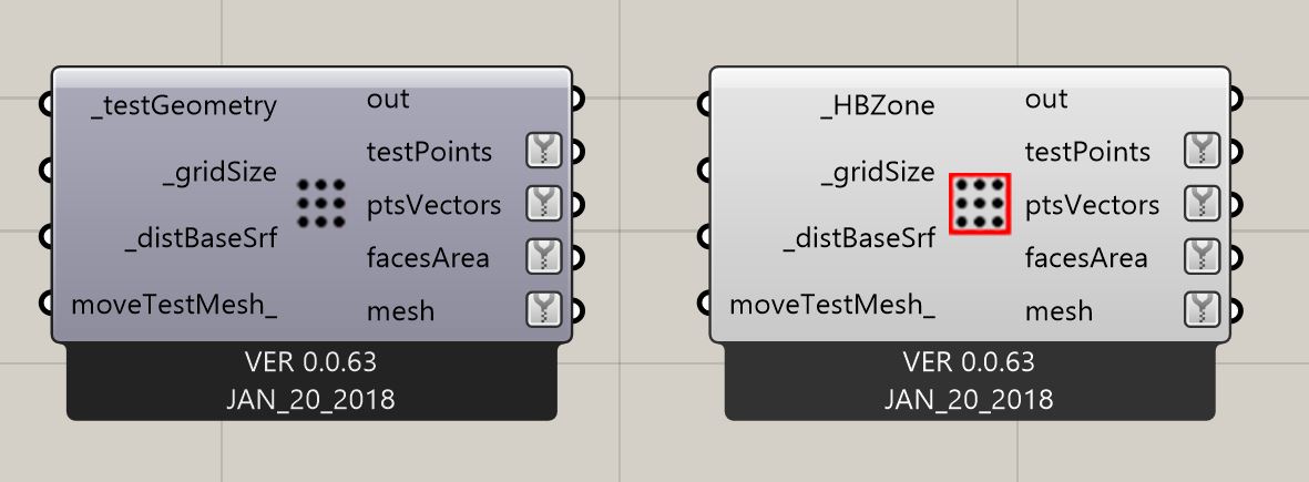
The one on the right i sthe one you use (genHBZoneTestPts). It creates the test surface from the floor of the zone. It makes easy for the user since you don’t need to connect a specific geoetry but the zone.
The one on the left (genTestPts) is for more generic cases, and it is not related directly to the zone geometry. This is the one i meant in my response. For your case i recommend it … if you have an irregular geometry.
If you floor is just a rectangle then you are set with the first one.
Hope it is clear(er) now. Sorry for not paying attention carefully to the component you choose.
-A.
You can generate the points using any component. You are not limited to the two components that Honeybee provides but test points and vectors should have the same structure (number of branches and list length).