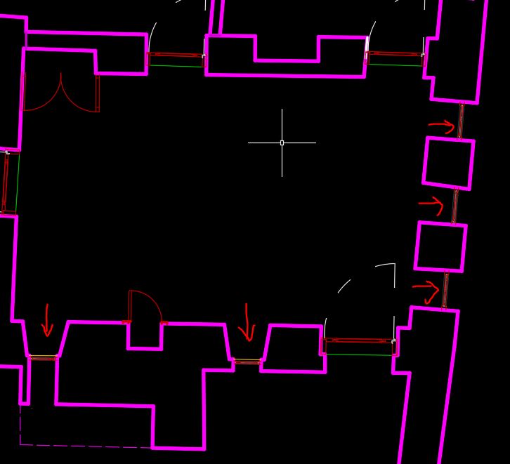
This image shows the floor plan of a historical house. The walls are drawn in pink, and the areas marked with red arrows indicate the locations of the windows.
I am conducting a thermal comfort analysis using Grasshopper and Honeybee.
For this purpose, I would like to ask: from which line should I draw the wall boundary — from the inner face of the wall or the outer face?
I would really appreciate your help and guidance on this.
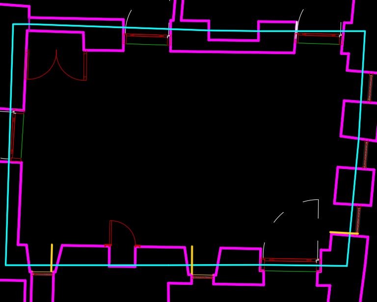
Thank you very much. In the plan, the polyline drawn in blue represents the wall centerline. However, when I draw the polyline from the center, I encounter issues at the locations marked in yellow where there is window depth. How can I account for that? For this reason, I initially drew the polyline along the inner wall face.
I’ve read that in the construction set, the defined wall thickness is applied outward from the polyline. In that case, what should I do?
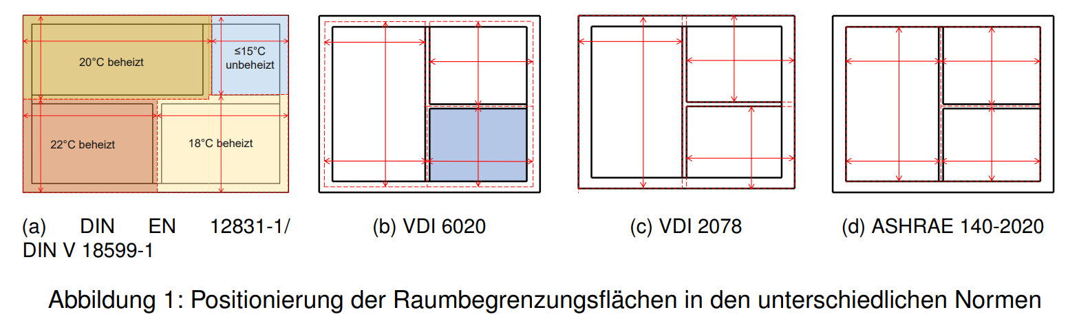
You may find more information about so-called space boundaries in this paper. Unfortunately, it’s in German, but you can use DeepL or other tools to translate it:
Geometrische Transformation von IFC-Raumbegrenzungsflächen für die normkonforme thermische Gebäudesimulation (Geometric transformation of IFC room boundary surfaces for standard-compliant thermal building simulation)
In: Proceedings of 33. Forum Bauinformatik : 07.- 09. September 2022
doi:10.14459/2022md1686600
Link: https://mediatum.ub.tum.de/doc/1686600/1686600.pdf (Page 283)