Interzone Airflow

Hi @devang

Here I came to a question … Consider you need to set cross ventilation for the space, as here we have two air walls, the input “interzoneflowrate” should get a value , in reality or other modelling when I added an air wall on purpose (not like this that we had to separate because of the non-convex issue and assign air walls), I do a CFD simulation at a peak time to calculate that inter-zone air flow rate, but in this case do you have any suggestion how we should re consider the inter-zone flow rate?

Hi @AMIRTABADKANI,

I assume that you use CFD simulation to derive the flow rate and then use ZoneMixing object to assign flow rates. If this is what you are already doing then I do not have any suggestion at the moment. We may have more flexibility when the Airflow Network is implemented in Honeybee. On that thought, I also think you can make use of Airflow network using the additionalStrings_ input on Honeybee_Run Energy Simulation component.

1 Like

Thanks @devang,

Do you have any sample of this additional string that can be implemented into simulation ?

@AMIRTABADKANI

Are you are calculating just single flow rate value from the CFD (at peak time) and using that as a constant interzone air flow rate? If you have a building where the natural airflows are complex (i.e ventilation schedule, significant wind loads, multiple adjacent zones), I wouldn’t trust a single value to capture the interzone flow rate.

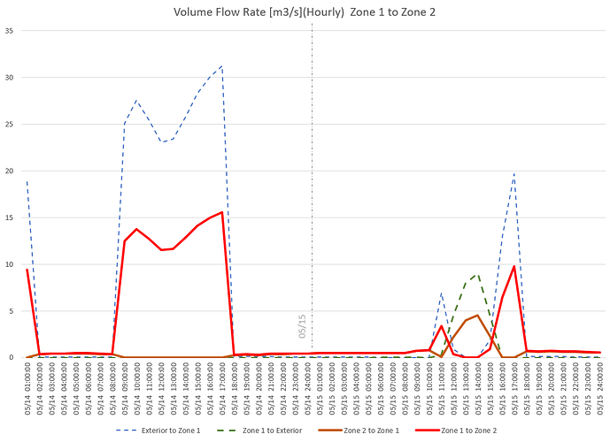
To provide some context, here’s an example of the interzone volume flow rate over two days that I calculated for two zones using the Airflow Network. Dotted lines are flow rates from operable windows to indoors, and the red line indicates the flow from zone 1 to zone 2 through transfer grilles. As you can see the flow rate changes from 0 to 15 m3/s from zone 1 to 2 on the first day, and on the second day the airflow reverses itself and zone 2 flows into zone 1 for a while.

So, depending on how accurate your model needs to be, and how complex the airflow dynamics are, you may need to capture flow rates at various intervals in your CFD, and abstract a sort of step function to create a schedule of interzone flow rates to capture these kinds of changing flow rates over time.

@SaeranVasanthakumar

Thanks for your reply ,
I agree with you completely without any doubt … But as far as I know in Honeybee air flow settings , this inter-zone air flow rate is a single number that should be assigned to an existing air wall (Only) unless I change it through its schedule which I still think its not accurate enough even just by adding coefficients … However I know this component has not been designed for calculating air flows between adjacent zones , but I believe this is sth which is really necessary for a simulation … and I need to find a way to do it in Honeybee for one of my projects … especially when I have indoor windows which are operable to adjacent zones like an atrium…

CreatingCusomMixObjects.gh (512.6 KB)

Credit for this file goes to @chris. Here the ZoneMixing object is used.

In your case where you have operable windows between zones I would recommend using Air-flow network. Which will account for factors such as buoyancy flows, pressure differences, the opening size, when a window is open. In a typical Energyplus installation, you will have example files making use of the Air-flow network. They should help.

1 Like

@AMIRTABADKANI

You can set a schedule for fractional interzone flow rates using the Honeybee_Set EP Air Flow components. Specifically you would set the interZoneAirFlowRate_ and interZoneAirFlowSched_ to precalculated values.

The more precise way to integrate air flow rates, is to do what @devang suggests, and integrate the Airflow Network method. It is kind of complicated though, and I think it helps to have some experience editing .idf files before attempting to do it. Here’s an example idf file that will give you an idea of what integrating the AFN looks like in terms of writing it out as an ‘additionalStrings’ input.

Basically, at minimum you have to define within the AirflowNetwork group:

  • SimulationControl
  • MultiZone: Zone
  • MultiZone: Surface
  • MultiZone: Surface: Crack
  • MultiZone: Component: SimpleOpening

And then various output variables to verify its working correctly. Let us know if you are planning on attempting this, and post some of your efforts, we can provide some advice about what inputs and outputs you need to set.

1 Like

Hi @SaeranVasanthakumar and @devang

I really appreciate your shared thoughts …

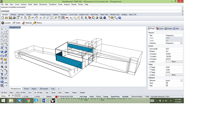
Somehow based on the available examples I wrote an additional string … just to clarify, I would like to have an inter-zone natural ventilation only between three adjacent zones: SouthOff, Atrium and OfficeUp…
As you see in the picture The atrium is between two other zones …

but for MultipleZone: Surface part, Do I need to define all the surfaces individually or only those which are supposed to have operable interior windows ( that are shown in the picture)?

Here is the written part till now :

AirflowNetwork:SimulationControl,
AirflowNetwork_All, !- Name
MultizoneWithDistribution, !- AirflowNetwork Control
Input, !- Wind Pressure Coefficient Type
OpeningHeight, !- Height Selection for Local Wind Pressure Calculation
LOWRISE, !- Building Type
500, !- Maximum Number of Iterations {dimensionless}
ZeroNodePressures, !- Initialization Type
1.0E-05, !- Relative Airflow Convergence Tolerance {dimensionless}
1.0E-06, !- Absolute Airflow Convergence Tolerance {kg/s}
-0.5, !- Convergence Acceleration Limit {dimensionless}
0.0, !- Azimuth Angle of Long Axis of Building {deg}
1.0; !- Ratio of Building Width Along Short Axis to Width Along Long Axis

AirflowNetwork:MultiZone:Zone,
SouthOff, !- Zone Name
Temperature, !- Ventilation Control Mode
WindowVentSch, !- Ventilation Control Zone Temperature Setpoint Schedule Name
0.3, !- Minimum Venting Open Factor {dimensionless}
5.0, !- Indoor and Outdoor Temperature Difference Lower Limit For Maximum Venting Open Factor {deltaC}
10.0, !- Indoor and Outdoor Temperature Difference Upper Limit for Minimum Venting Open Factor {deltaC}
0.0, !- Indoor and Outdoor Enthalpy Difference Lower Limit For Maximum Venting Open Factor {deltaJ/kg}
300000.0, !- Indoor and Outdoor Enthalpy Difference Upper Limit for Minimum Venting Open Factor {deltaJ/kg}
VentingSCH; !- Venting Availability Schedule Name

AirflowNetwork:MultiZone:Zone,
Atrium, !- Zone Name
Temperature, !- Ventilation Control Mode
WindowVentSch, !- Ventilation Control Zone Temperature Setpoint Schedule Name
0.3, !- Minimum Venting Open Factor {dimensionless}
5.0, !- Indoor and Outdoor Temperature Difference Lower Limit For Maximum Venting Open Factor {deltaC}
10.0, !- Indoor and Outdoor Temperature Difference Upper Limit for Minimum Venting Open Factor {deltaC}
0.0, !- Indoor and Outdoor Enthalpy Difference Lower Limit For Maximum Venting Open Factor {deltaJ/kg}
300000.0, !- Indoor and Outdoor Enthalpy Difference Upper Limit for Minimum Venting Open Factor {deltaJ/kg}
VentingSCH; !- Venting Availability Schedule Name

AirflowNetwork:MultiZone:Zone,
OfficeUp, !- Zone Name
Temperature, !- Ventilation Control Mode
WindowVentSch, !- Ventilation Control Zone Temperature Setpoint Schedule Name
0.3, !- Minimum Venting Open Factor {dimensionless}
5.0, !- Indoor and Outdoor Temperature Difference Lower Limit For Maximum Venting Open Factor {deltaC}
10.0, !- Indoor and Outdoor Temperature Difference Upper Limit for Minimum Venting Open Factor {deltaC}
0.0, !- Indoor and Outdoor Enthalpy Difference Lower Limit For Maximum Venting Open Factor {deltaJ/kg}
300000.0, !- Indoor and Outdoor Enthalpy Difference Upper Limit for Minimum Venting Open Factor {deltaJ/kg}
VentingSCH; !- Venting Availability Schedule Name

AirflowNetwork:MultiZone:Zone,
DinningRoom, !- Zone Name
Novent, !- Ventilation Control Mode
, !- Ventilation Control Zone Temperature Setpoint Schedule Name
0.3, !- Minimum Venting Open Factor {dimensionless}
5.0, !- Indoor and Outdoor Temperature Difference Lower Limit For Maximum Venting Open Factor {deltaC}
10.0, !- Indoor and Outdoor Temperature Difference Upper Limit for Minimum Venting Open Factor {deltaC}
0.0, !- Indoor and Outdoor Enthalpy Difference Lower Limit For Maximum Venting Open Factor {deltaJ/kg}
300000.0, !- Indoor and Outdoor Enthalpy Difference Upper Limit for Minimum Venting Open Factor {deltaJ/kg}

AirflowNetwork:MultiZone:Zone,
Corridor, !- Zone Name
Novent, !- Ventilation Control Mode
, !- Ventilation Control Zone Temperature Setpoint Schedule Name
0.3, !- Minimum Venting Open Factor {dimensionless}
5.0, !- Indoor and Outdoor Temperature Difference Lower Limit For Maximum Venting Open Factor {deltaC}
10.0, !- Indoor and Outdoor Temperature Difference Upper Limit for Minimum Venting Open Factor {deltaC}
0.0, !- Indoor and Outdoor Enthalpy Difference Lower Limit For Maximum Venting Open Factor {deltaJ/kg}
300000.0, !- Indoor and Outdoor Enthalpy Difference Upper Limit for Minimum Venting Open Factor {deltaJ/kg}

@AMIRTABADKANI

I believe you do have add all zone surfaces, and define some sort of leakage components for the surface. So for example if you don’t have a wall or a door, you must define a crack.

Example of referencing the crack:

    Zn001:Wall002,           !- Surface Name
    CR-1,                    !- Leakage Component Name
    WFacade,                 !- External Node Name
    1.0;                     !- Window/Door Opening Factor, or Crack Factor {dimensionless}

And then you have to define the Crack object in the AFN object like so:

    CR-1,                    !- Name
    0.01,                    !- Air Mass Flow Coefficient at Reference Conditions {kg/s}
    0.667;                   !- Air Mass Flow Exponent {dimensionless}

I’m currently travelling and attending in a conference, so can’t elaborate further but hope that helps. I can take a better look next week.

1 Like