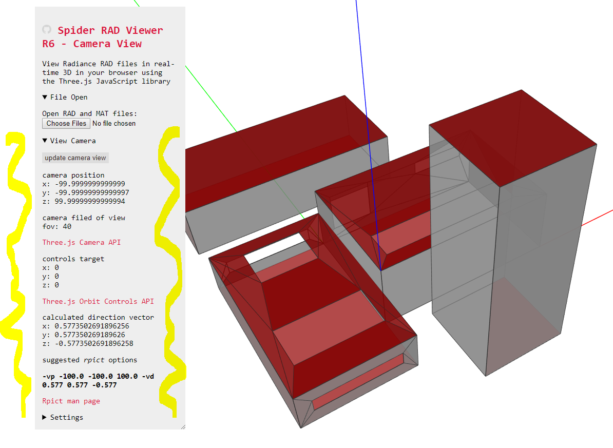
I have added displaying rpict parameters to the wish list. It may take me a bit of time to figure these things out.
What I will work on today is a read out of the current camera viewpoint and direction in the Spider RAD Viewer. Fingers crossed, this will allow you to copy paste the parameters from the viewer to the rpict command line or batch file.
this is perfect. And several times faster than the native radiance method.
I wasn’t counting you getting this to work so quickly!
Nice on all counts and my pleasure. And thank you for sharing your text case images
Hm, it looks like if I put tabs between the values, they might be easier to copy and paste. I have changed the text between the values from spaces to tabs. This could help you copy and paste the the xyz values all at once.
Two questions:
What would you like to see next in Spider RAD Viewer?
How long does it typically take to create rpict renderings given the normal level of building complexity in your office?
@TheoA I am (currently) a researcher, so I don’t run into nearly as many complex models as I used to before. Rpict renderings can take a really long time to render depending on the complexity of the model. It is possible, however, to do selective optimization by excluding certain materials from participating in ambient calculations.
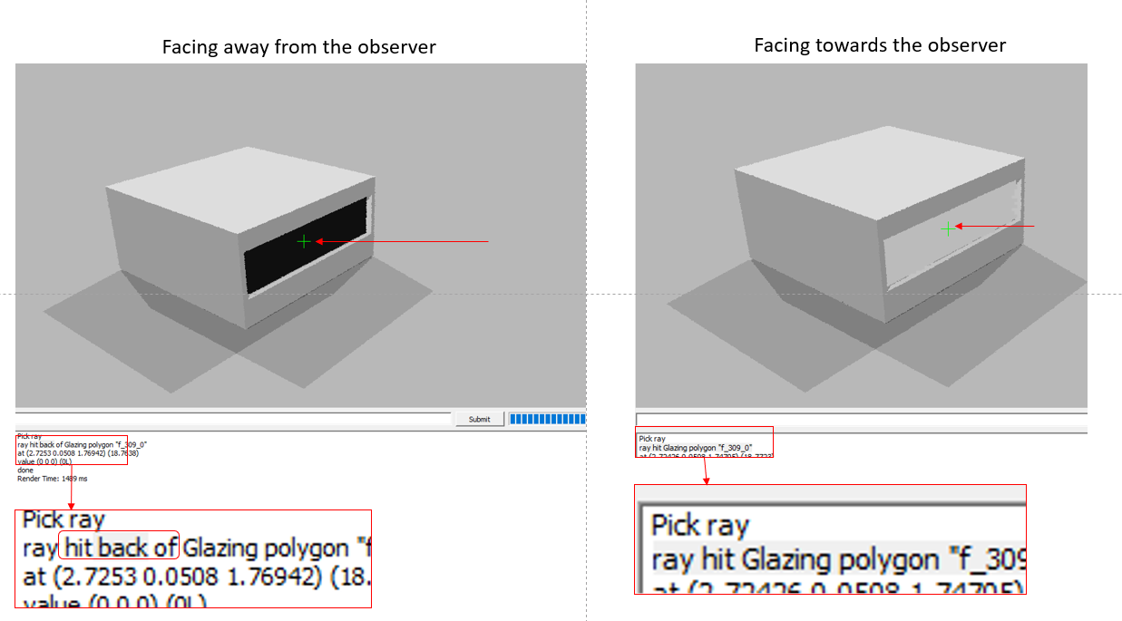
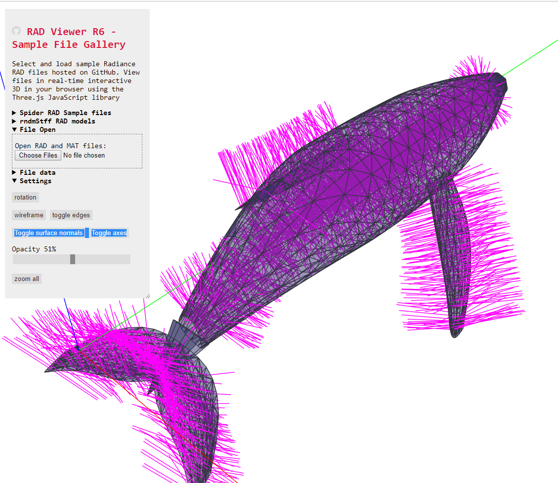
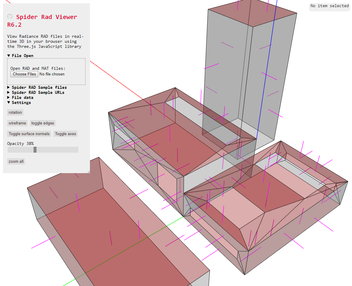
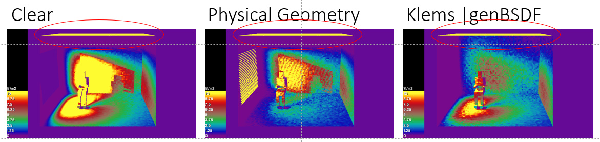
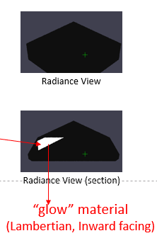
The one thing that might be useful for everybody going forward is the ability to know if the surfaces are correctly oriented. For all the multi-phase calculations that we have implemented Honeybee[+], the orientation of the glazing surface is critical. Within Radiance one can do this by tracing a single ray to surface or by assigning directional materials like “glow” or “bsdf” to them… Glow, for example, renders as completely black if the surface is facing in a direction opposite to the camera.
Both of those methods are fairly clumsy. This might be something that you could address through an existing method in the three.js API. If one could know the orientation of the normal of a surface through an arrow or something similar it will be pretty useful.
(For all the grasshopper based workflows, Mostapha has put in some checks to ensure that the orientation of the glazing (correctly) faces inwards. However, once we starting adding non-Grasshopper based geometry there is no way to keep track of orientations).
The code is a work-in-progress and only works on some geometries. For example, the normals do not show on the fast triangles-only cookbook script (yet).
BTW, adjusting the opacity helps you see the normals inside a building.
Future revisions of the viewer will show normals for all supported geometry types.
Also it might be nice for a normal to appear when you click on a surface to display its info in the pop-up area. Even better: a button in the pop-up that allows you to flip the normal and save the edits to a new file.
@sarith: you make good suggestions (ones I can do anyway). Thank your for taking the time to do this. Fingers crossed this all helps people make better Radiance images faster with less slogging through menial work.
This (too) was super quick! So here is another one: Would it be possible to draw a rectangle around some geometry within the view-port and get the extents of the surfaces contained within that rectangle (like a bounding-box)? Like getbbox? Getbbox, while being extremely fast, just spits out six numbers. And the problem is that a lot of times while using a utility likegenBSDF, just knowing the bounding a box value itself is not enough.
By the way, here is a usecase for bounding box from the genbsdf manpage… The geometry must fit a rectangular profile, whose width is along the X-axis, height is in the Y-axis, and depth is in the Z-axis. The positive Z-axis points into the room, and the input geometry should not extend into the room. (I.e., it should not contain any positive Z values, since the putative emitting surface is assumed to lie at Z=0.) The entire window system should be modeled, including sills and edge geometry anticipated in the final installation, otherwise accuracy will be impaired. Similarly, materials in the description should be carefully measured.
(For all the grasshopper based workflows, Mostapha has put in some checks to ensure that the orientation of the glazing (correctly) faces inwards. However, once we starting adding non-Grasshopper based geometry there is no way to keep track of orientations).
I am a Radiance newbie so apologize if this is a naive question. But doesn’t Radiance follow the graphics convention of ordering all surfaces edges counter-clockwise? Why can’t you just check/confirm normal orientation simply by taking the cross-product of the edges, and making sure the normal is pointing outside of a closed curve representing the floor? Should work for any code, assuming edges are ccw.
What a fun challenge! Thank you. Three.js has some really nice bounding box tools, so this should be possible.
But not today.
I am building R7 - which should include the fast drawing code for triangles and quads and drop to the slower more more complex code for polygons with five vertices or more - like the ten vertex polygons with ‘openings’.
Also I will spend a few days in the California Central Valley, so don’t expect much before this weekend.
And this will give me more of a chance to consider the workflow in your good request.
@SaeranVasanthakumar it does follow CCW ordering and the orientation of the surface itself is determined by vertex ordering. The issue is that in Radiance, except for certain specific types of simulations there is no concept of indoor and outdoor, so one has to start by identifying which surface is what and then go about scripting vector math (which is what I have done in the past using euclid.py and such). Additionally, all light sources are directional surfaces too. If you have a light fixture inside the room, there is no singularly correct vertex ordering for that light surface as it could be an uplight or a downlight.
If you are exporting a raw model from something like Sketchup or AutoCAD there is fair chance that you will run into surfaces with “incorrect” vertex ordering.
Thanks for explaining that to me, that is much more complicated then I realized. And I can certainly see the usefulness of having a tool to display and flip the surface normals.
Would it be possible to draw a rectangle around some geometry within the view-port and get the extents of the surfaces contained within that rectangle (like a bounding-box)?
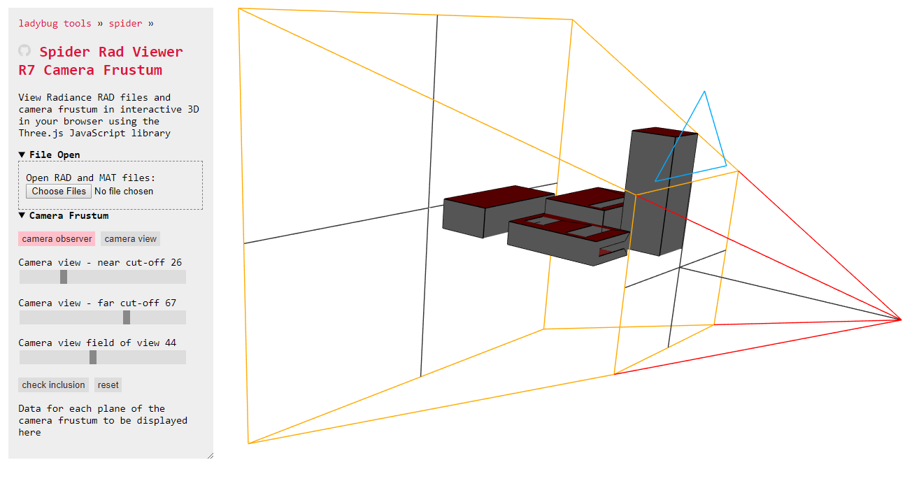
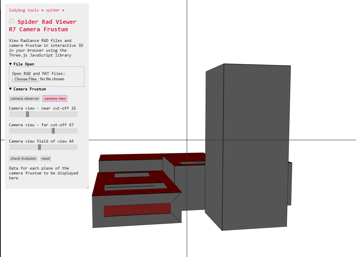
I am back at the keyboard after a few days of travel. There’s a new Spider RAD Viewer Cookbook script which does not precisely match your request but is quite close and it responds to one of my interests. The script helps you view and edit the frustum of a selected camera. Future revisions will allow you to observe and edit purely rectilinear boxes.
In the mean time can you point me to the Radiance man page that describes the notation required by Radiance when the six planes of a box are asked for?
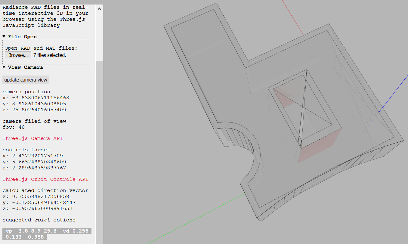
@TheoA Would it be possible to match this to Radiance views? If yes, this is actually far more useful than the bounding box stuff that I was asking for. I never realized this functionality was within the scope of the 3.js API. Here are a couple of use cases from a recent project:
In the above image, I am trying to look outside and inside at the same time. The external ceiling surface highlighted by the red ellipses in each of the figures, tells me that a large amount of radiation is indeed falling on the room. The interior view gives an idea of the impact of choosing the fenestration system.
The above image is a part of an energy-balance test where we needed to be sure that the surface orientations were correct. Again the internal-external view is required to ascertain if the setup is correct (this is also addressed by your surface normals script now).
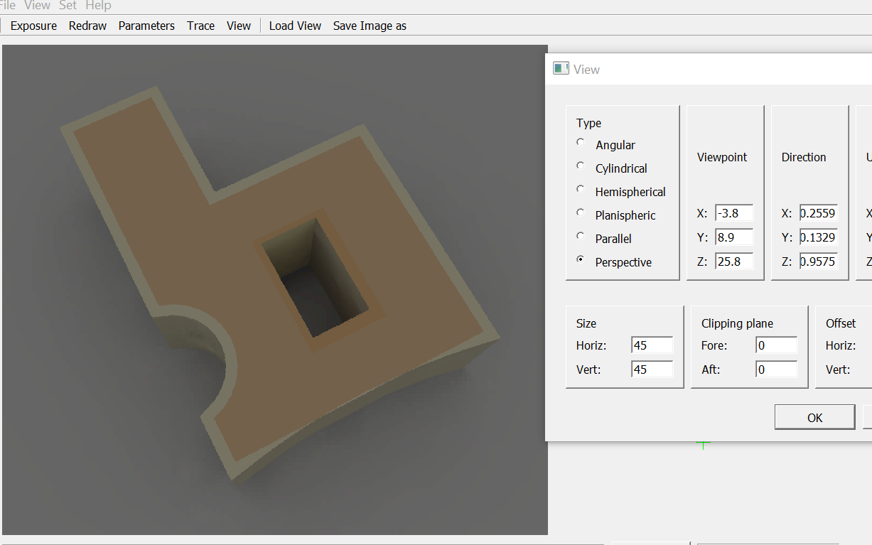
In rpict and all the other image-based radiance tools, these options are incorporated through -va and -vo for “aft” and “fore” respectively (see below in bold).
Regarding your first question, the man page for getbbox is here. The output for the above model looks something like this:
In Radiance, all of this is commandline and not interactive at all. So, if one has to just calculate the extents of specific aspects of the scene, it is a lot of work.
There are a ton of visual errors and a ton of error messages in the JavaScript console and the interaction runs at about one frame per second. On the other hand 400,000 triangles and half a million lines are appearing in my Chrome browser on a Win10 core i7 with Nvidea GPU laptop.
I plan to spend the next couple of days fixing things up and getting R7 to be the stable release. It’s not ready yet, but fingers crossed you will be able to load good sized models without too many issues and prepare better parameters for you Radiance runs.
[ After that I plan to take the new tricks I have learned here and carry them over to R15 of the Spider ‘Aragog’ gbXML Viewer. ]
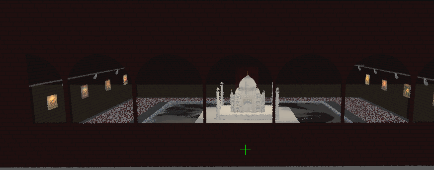
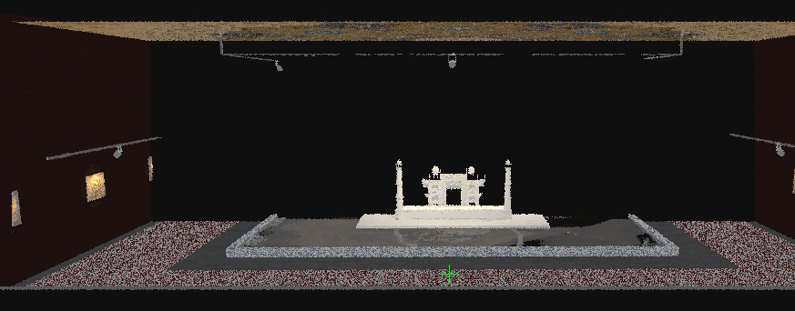
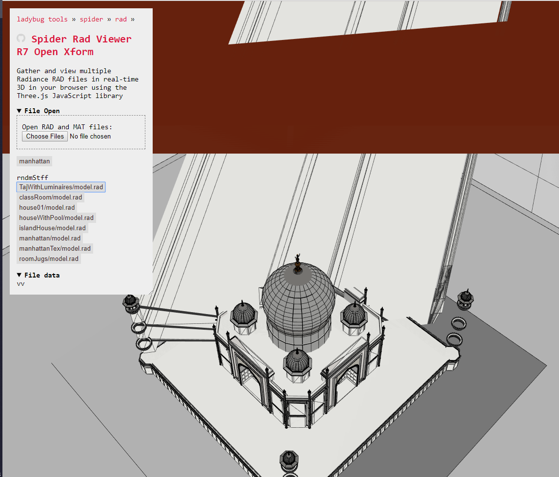
Hi @TheoA, I am not sure if that particular model (Taj Mahal) is a good representation of complexity. It is a hodgepodge of geometry from a model from 3D warehouse, manually placed light fixtures, hacky textures etc. I had worked on it as a choose-your-own-model homework assignment while in gradschool. I was curious to see if Radiance could handle all that complexity. We Indians have a penchant for re-imagining Taj Mahal in different ways and forms…this one went slightly overboard!
Anyway, if the Rad Viewer can handle large exports from Rhino and Revit, that should be more than enough. I dont really foresee 99% of the Radiance users creating Radiance models by manually typing in geometry.
Back to our original discussion, this…
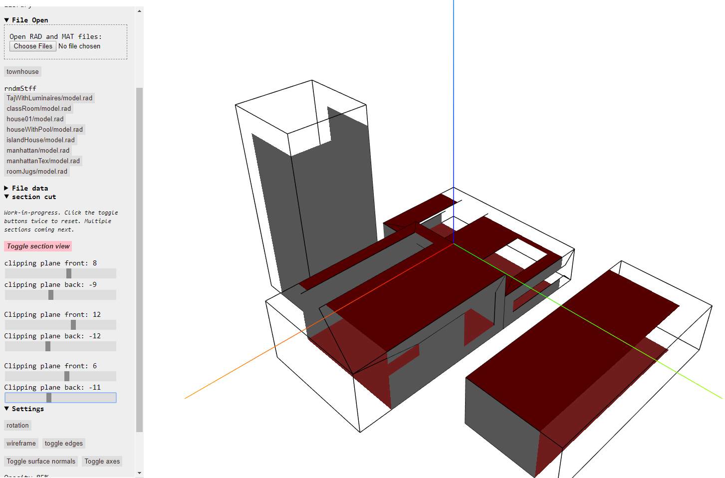
Multiple sections may be cut through a model and their location updated in real-time
…if linked to view properties (-vp -vo etc) would be great!
Your files in rndmStff are probably the most interesting to play with currently. But once there a good workflow going with Rhino and Revit, fingers crossed there will be even more interesting files to play with including de-constructed post-modern Bibi Ka Maqbara remixes.
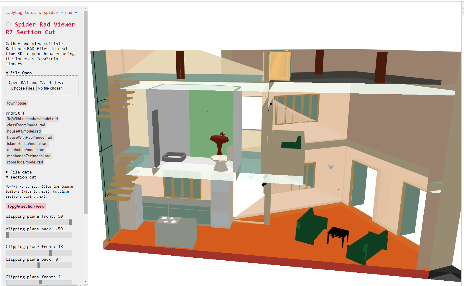
Cutting sections
Back to our original discussion, this…
Multiple sections may be cut through a model and their location updated in real-time
…if linked to view properties (-vp -vo etc) would be great!
Here is the ‘Townhouse’ sample file in a still very preliminary Spider RAD Viewer R7 with a new additional cookbook script that cuts sections through a RAD file model
Click ‘toggle section view’ to start the drag the sliders.
Note that the files in the menu are test files and all have issues. House01 and townhouse re probably the safest to try.
The next step will be to output numbers that Radiance understands.
But the even more important next step will be to get RAD Viewer R7 to be reasonably nice and stable. This is so I can go back to gbXML Viewer for a while and help @MichalDengusiak with his upcoming seminar
@TheoA Multiple planes in the same view port is interesting. This is something that isn’t done in (standard) Radiance. Back in 2002, John Mardaljevic and Greg Ward had a formulated a new workflow to do arbitrary clipping planes. I think we can channel the outputs from your viewer into a generalized workflow for arbitrary clipping planes (I will come up with the inputs for Radiance).
By the way, is this the link for the stable version of the RadViewer?
@sarith great idea. We also discuss with @TheoA to allow linking spaces with results and give an option to export chosen spaces from gbXML model to into RAD.
This is a link to always latest version here RAD Viewer
For what it worth, have you tried the one with Honeybee[+]? This doesn’t try to create the surfaces so it’s not neccassary useful for recreating the model but it is useful for visualization, and well you can modify the code to generate meshes or surfaces if that’s what you need.
import Rhino.Geometry as rg
from honeybee.radiance.radparser import parse_from_file

fp = r'PATH_TO_RAD_FILE'
objects = parse_from_file(fp)
polylines = []
for obj in objects:
    pl = rg.Polyline()
    coords = map(float, obj.split()[6:])
    for i in range(int(len(coords) / 3)):
        pl.Add(coords[3 * i], coords[1 + 3 * i], coords[2 + 3 * i])
    pl.Add(coords[0], coords[1], coords[2])

    polylines.append(pl.ToNurbsCurve())
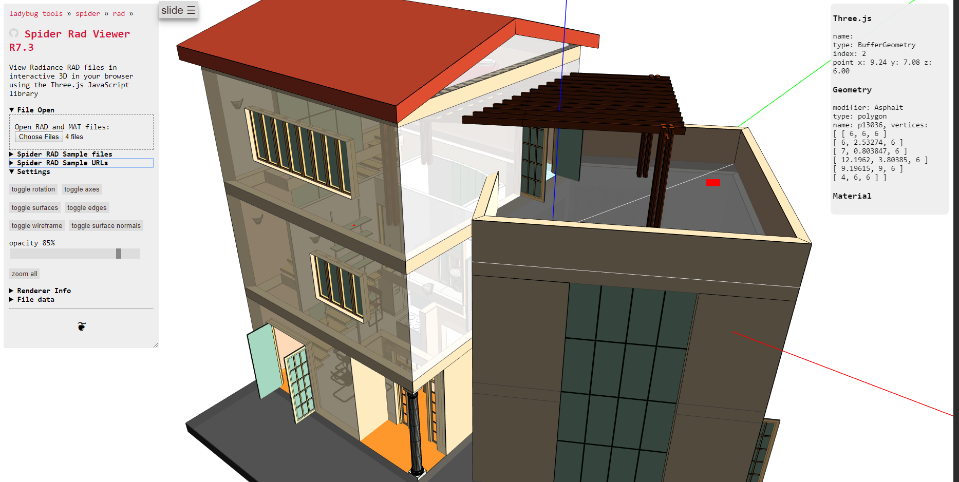
In previous releases the wall around the windows are very broken. But not any more!
And there’s a new ‘slide’ button so you can view RAD files in 3D on your phone.
The app, as a whole, seems to be settling down. So soon it will be time to be cleaning up the code, fixing smaller bugs, making things faster - and adding new features.