@matrameUK
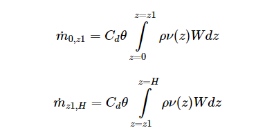
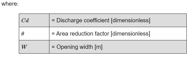
Geometrically, the panel discharge coefficient is affected by two factors: 1) the effective area by through air is flowing (Area holes), 2) the way this air is distributed/flowing through the holes. This second factor explains why adopting a new equivalent area to describe the problem is not enough and why a proper discharge coefficient should reflect that the air flow shape has changed.
This is a good summary, and since it’s clear that the resulting air flow resistance depends a lot on the type of orifice in the screen, I’m going to backtrack from my previous assertion that the perforations will create faster flow for an equivalent window area, and just say I’m not sure. I’ll explain my reasoning for my uncertainty below.
Considering this reasoning, cracks/perforations should reflect lower discharge coefficients than conventional windows because of the air resistance descried above and air speeds decreasing. Do you agree?
Can you clarify a bit more why you think it’ll be slower? We know that for a given window area, the Cd is lower assuming that the same window area has some obstruction, like an insect screen. But if we reduce the window area to account for that surface obstruction (thereby proportion reducing the volumetric flow by that area reduction) how do we know if the Cd we assign to that reduced area is lower or higher?
If you look at the formula for crack flow (used to model infiltration in EP[1]):
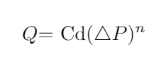
There’s two unknowns, the Cd, and also n (what I referred to as the pressure exponent), which is set as 1/2 for windows or large orifices, but can be as big as 1 for small orifices which exhibit laminar flow[2]. So basically resistance is proportional to velocity for small cracks, and proportional to the square of the velocity for large cracks. Hutcheon and Handergord[2] suggest a Cd of 0.6 for cracks, but the n is dependent on the type of orifice, which at the laminar extreme seems would increase wind flow (for dP >= 1). If you had one small hole in your screen, with laminar flow, and you wanted to model it as a window with equivalent area, you’d actually have to increase the Cd of that window (since there’s no n-parameter to adjust in the window model, you have to account for the velocity increase with the Cd).
It seems like you can get a wide range of behavior by varying screen parameters, and so requires more dedicated research. That’s why I think my earlier suggestion, which was based on reasoning about crack flow dynamics, is too simplistic to deal with the perforated screen scenario. It doesn’t account for interference, and didn’t make enough of a distinction between types of orifices.
If it were me, I would just model multiple parameters, and calculate the mean and a confidence interval from the resulting distribution. It may even be the case that you can be 95% confident of a very narrow range of building performance even with a wide range of discharge coefficients (especially given that the Cd only effects the stack effect, not window driven ventilation). It would be more work, but given how many parameters in EP’s airflow models are fixed by simplifying heuristics, it’ll be more accurate.
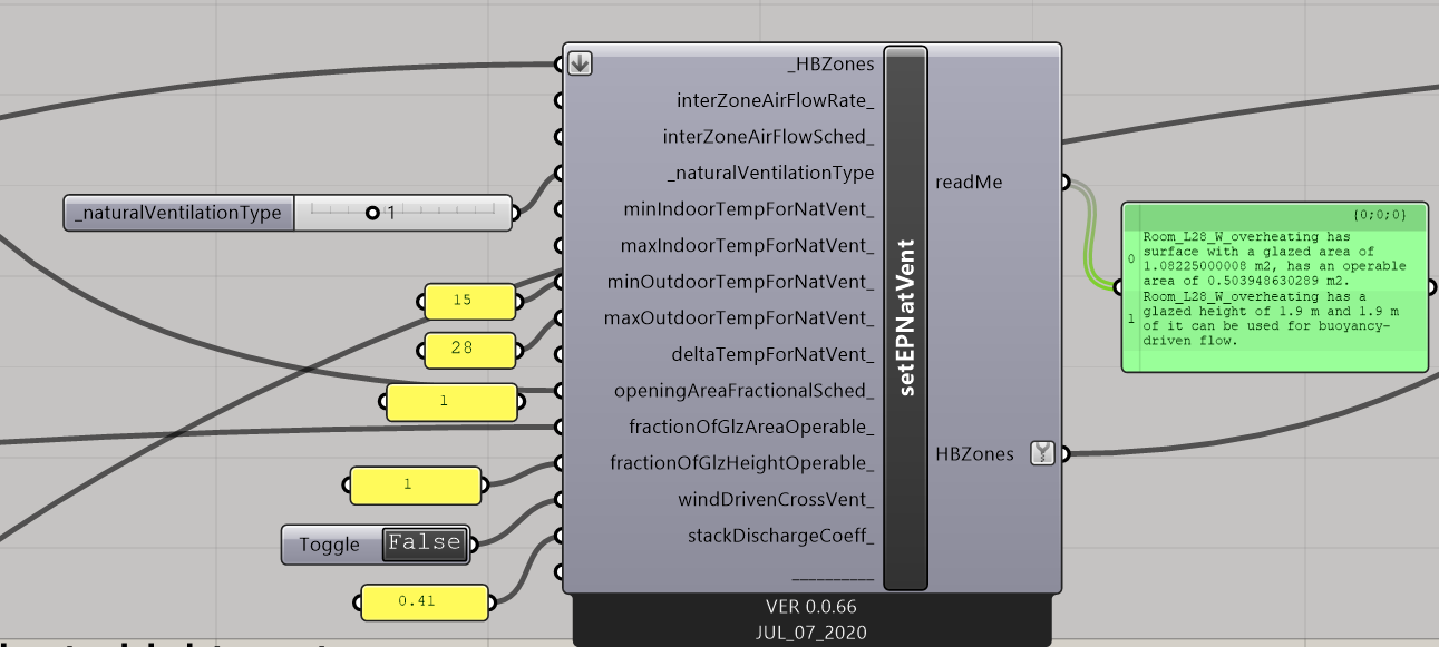
I never used the AirflowNetwork component but I’m happy to consider that if is more suitable. If I got your point, the setEPNatVent is not able to take into account supply and return leaks from the same window which is providing a double air flow through its opening. Correct?
Yes, I think AFN is the way to go.
[1] Group – Airflow Network: Input Output Reference — EnergyPlus 9.3
[2] The chapter on air leakage in Hutcheon and Handergord’s “Building Science for a Cold Climate”.