Thanks, @mostapha . What you noted partly explains what is going on here.
A cooling design day profile with negative opaque conduction is very common for mid-to-high latitude climates like New York or Boston, particularly during nighttime hours of the cooling design day. This is because, even on the warmest days of the year, you can still get the outdoor air temperature dropping below the indoor room air temperature, meaning that heat is going to conduct through the walls from inside to outside, resulting in a negative conduction term. This is what Mostapha was referring to.
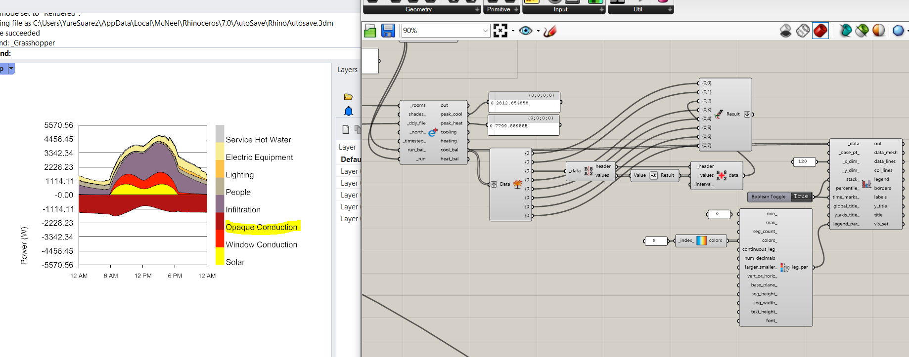
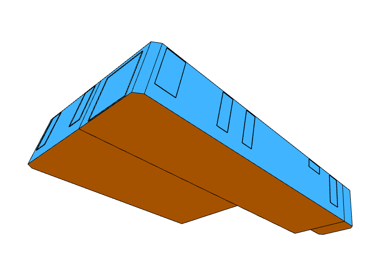
However, what you have going on here, @Yure, is different because you are running this simulation in Houston Texas. Also, the fact that the infiltration term is always positive is a dead giveaway that the outdoor air temperature is not dropping below the indoor air temperature. Let me first say that this is not a bug but taking a look at the boundary conditions of your model, I notice something important - all of your Rooms are in direct contact with the ground:
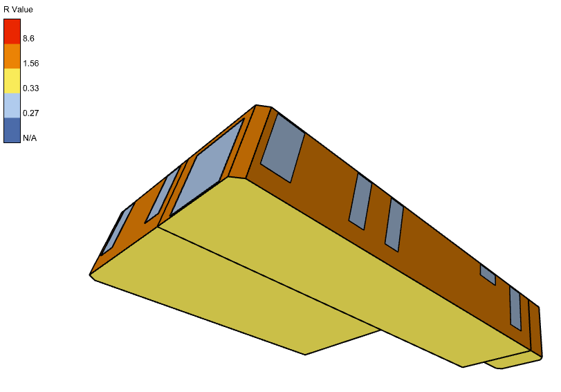
And the R-Value that you have for your slab on grade is not very high:
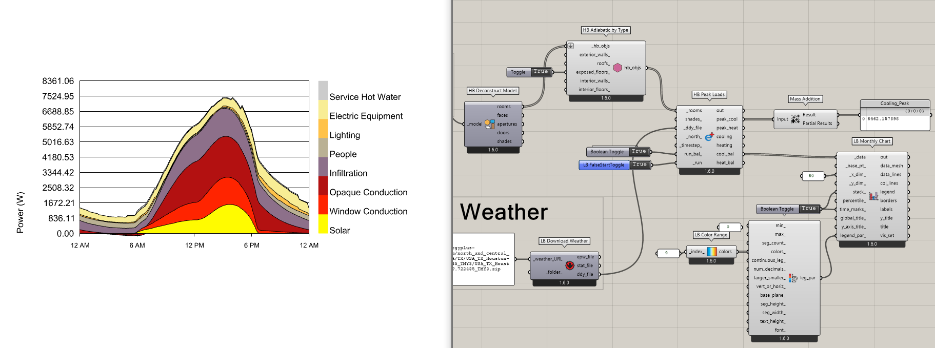
This means that most of that big negative conduction term actually represents is a whole bunch of thermal energy conducting from the inside of your building to the Ground, which far outweighs the conduction through other opaque Faces. So this is just EnergyPlus showing us exactly what we put into it. If you instead want to see a Cooling Design Day balance where the Opaque conduction is only the part through the Walls and Roof, then you can set the Floors of your model to be Adiabatic. This is what I did here and you can see that it’s probably closer to what you expect:
2023.0620 - Opaque Conduction Inquiry_CWM.gh (44.5 KB)
Now, there’s a big question about how realistic it is for the ground to help out so much on the Cooling Design Day or whether it really is better to be conservative and assume the Ground is Adiabatic. Certainly, we’re going to get some help from all of the Ground mass and it’s definitely going to lower the peak cooling compared to a case where we did not have a slab on grade. But the way EnergyPlus models the ground by default is very simple and may not be appropriate for your case here. That is, EnergyPlus assumes the Ground is at a constant 18C year round. This is usually not too far from the mark given that the Ground temperature on the other side of your floor will usually be somewhere between the conditioned Room air temperature and the average Meteoroligcal temperature of Houston, which I’m willing to guess is probably still less than 18C. But, if we’re being honest, the temperature of the ground for a case like this is probably more like 21C-23C and not as low as 18C. So, if you really wanted to produce a load profile close to reality, you can probably do this by bumping up the insulation and heat capacity of in your slab on grade construction to mimic the fact that you won’t get as much heat loss through the slab.
Or you can just take the conservative approach with the adiabatic ground. Honestly, I bet that is what a lot of MEP engineers would do in order to reduce their risk and liability.