Hi @chris, hi @mostapha.
I’m analyzing outdoor thermal comfort with Ladybug Tools 1.1.0. I want to calculate the UTCI and to calculate it I need MRT. I have a courtyard with a transparent ceiling and open in two directions. In the Human to Sky component there is the possibility to insert only the surfaces that block the direct sun and the view. Outdoor Solar MRT does not consider glazing, while Indoor Solar MRT yes. I want to know how window_trans assigns the value to the context.
Another way is with Honeybee infact I can also create a dummy box with AirBoundary conditions for vertical surfaces and calculate the MRT on the ground; for this solution is it possible to calculate the MRT based on a grid?
Or there is a way I’m not considering?
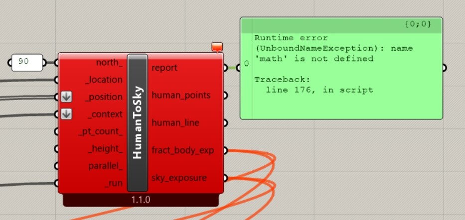
Beyond this I would like to highlight a problem that I don’t know if it has already been solved. Human to Sky component have a problem in north_ inpunt as show the picture. I fixed the error by correcting the python code, I just wanted to report this for the next updates.
It does not assign any transmittance to the context. It assumes that all of the context geometry is completely opaque. The transmittance is applied to everything else. So there’s an underlying assumption that any “unobstructed” view to the sky is through glass that has the input transmittance.
I am currently working on more sophisticated ways to map indoor comfort in the LBT plugin, which use EnergyPlus results. These will account for shortwave reflections and different transmittances through different Shade materials. I’m hoping to have these ready for the next stable release of the LBT plugin. If you really need something like this type of workflow now, you can use the legacy microcliamte mapping workflows:
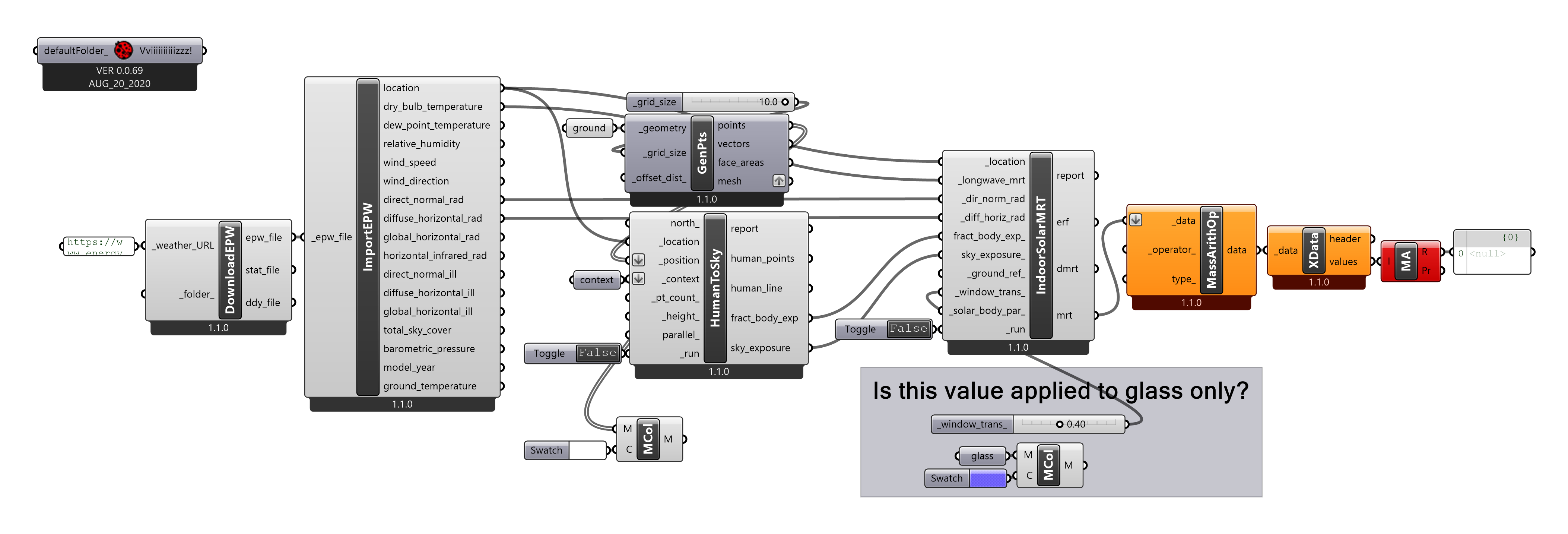
Hi @chris, I would like to show you this simple script and ask you if I understand.
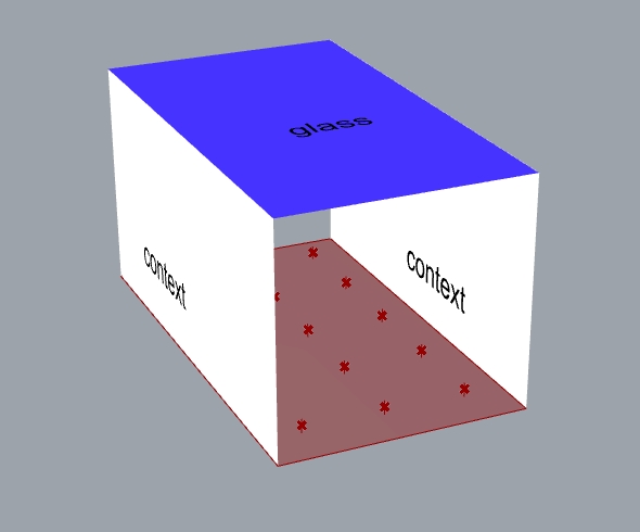
My doubt is how the “glass” component is considered if it is not attached anywhere.
Hi @nicmancio. As @chris chris mentioned above, except the opaque surface everything is assumed glass. For our above example, If you want to provide glass on top you just leave it blank and provide the transmittance value. Everything in the scene except the opaque surfaces, the values will be applied.
Hi @Asisnath. Thank’s for your reply.
I tried running the simulation with glass surface and without surface and the results are the same.
I tried to close the two open faces as glass and nothing, the result does not change.