Thanks for your question. Yes, I was trying to support the solar collector in Ironbug, but found it was not easy to do. So, I ended up commenting out the code for whenever it is ready for another round of try.
I will try to look into this over the weekend again, and will keep you posted.
Thank you very much for your time and effort. I really appreciate it.
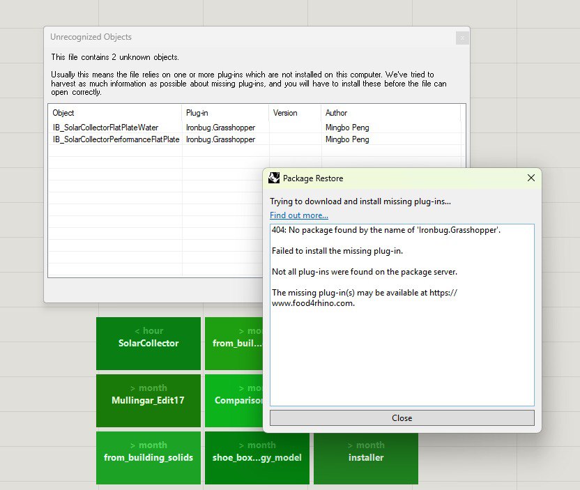
When I tried to open the .gh file, an installation window appeared. But it seems it fails to download and install the two objects.
I uninstalled the Pollination (1.57.2) and installed the newer one (1.57.3), but it seems the challenge still exists and I cannot have the two objects.
Kindly find the screenshot of the error message below.
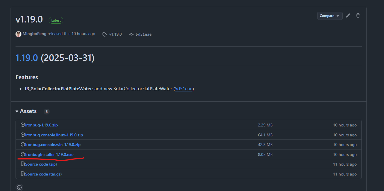
Hi @behnammmohseni, the new version of Ironbug has not been added to the Pollination installer. But you can just update it with the Ironbug installer that will override the older version from the Pollination installer. Release v1.19.0 · MingboPeng/Ironbug
Thank you for your efforts regarding the modelling of solar thermal collectors. I followed your template for my design. Unfortunately, I ran into some issues when simulating the system with EnergyPlus. Whenever I try to run it, I get the following error messages (see image). Do you know what I have to change?
Additionally, I would like to know if it is possible to change the material composition of the flat plate collector. For example, change the cover material (I assume that it is glass in the standard case) and adjust the thickness of the air cavity between absorber and cover.
You can find the above mentioned image bellow. Also you can find a download link for the gh file.
The example is just a guide on how to create a solar collector in IB. If you set all the canvases in the Rhino to Meter and put 2 for the run in the OS component, you will just have the .osm file that shows you the structure of the solar collector demand and supply side using the OpenStudio Application or the newly built component that will be released soon.
To run completely without error you need to have a real building, since the error you will see is the missing of the zone and not satisfying the heat balance equation.
For simulating a separate solar collector, there should be a separate engines, not HB model that is for the heat balance equation inside the house. Most of these engines is for Lady Bug tools (like solar paths, sky mask, etc.) and up to now, is not developed yet.
As an example the solar panel and the Electric Load that is previously developed, if you want to use, you need to have with buildings to solve the heat balance equation of the house, since all the shades in these components goes to something like HB Model.
Would it have something to do with the tank, due to its normal function as a thermal source (supply-side), not being written in as a demand side object correctly?
@MingboPeng I have a fully functioning system and building model that is returning this same error. It seems like the water heater component does not get modelled properly as a demand side object. Are you able to verify this and advise how it can be modelled on the demand side for the solar collector and the supply side for a hot water coil?
If so, you need to close the buffer tank loop completely, meaning that, the demand side of the buffer tank, should be the supply side for another loop.
You need to create another loop with something like baseboard, which the supply side is the buffer tank (that this buffer tank is the demand side of the solar collector)
Thanks for your reply. That was the issue except you cannot model this in ironbug
I did solve the issue for anyone looking for a workaround
in Ironbug i created two separate hot water loops
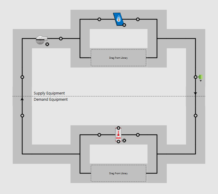
Solar collector loop
SUPPLY SIDE: solar collector, water-heater mixed with settings as storage/buffer tank, loop setpoint manager.
DEMAND SIDE: fluid-to-fluid HX
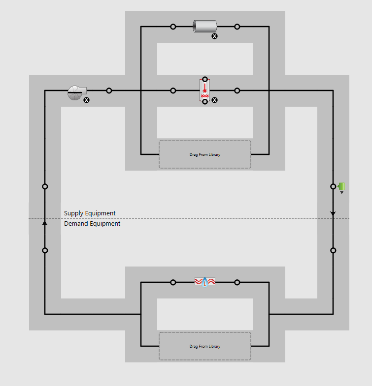
2.Heating coil loop
SUPPLY SIDE: fluid-to-fluid HX
.
DEMAND SIDE: hot water coils, loop setpoint manager
The fluid-to-fluid heat exchanger creates the correct nodes as a placeholder for the WaterHeater:mixed
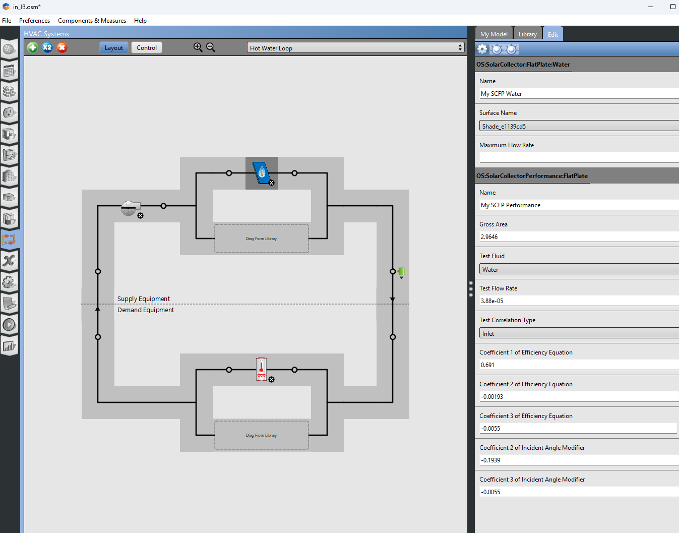
using Openstudio to visualise the node placement it is Fairly easy to edit the IDF file to replace the fluid-to-fluid heat exchanger with the WaterHeater:mixed buffer tank
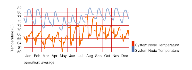
I used a system probe to track temperatures of the two loops and they look pretty good
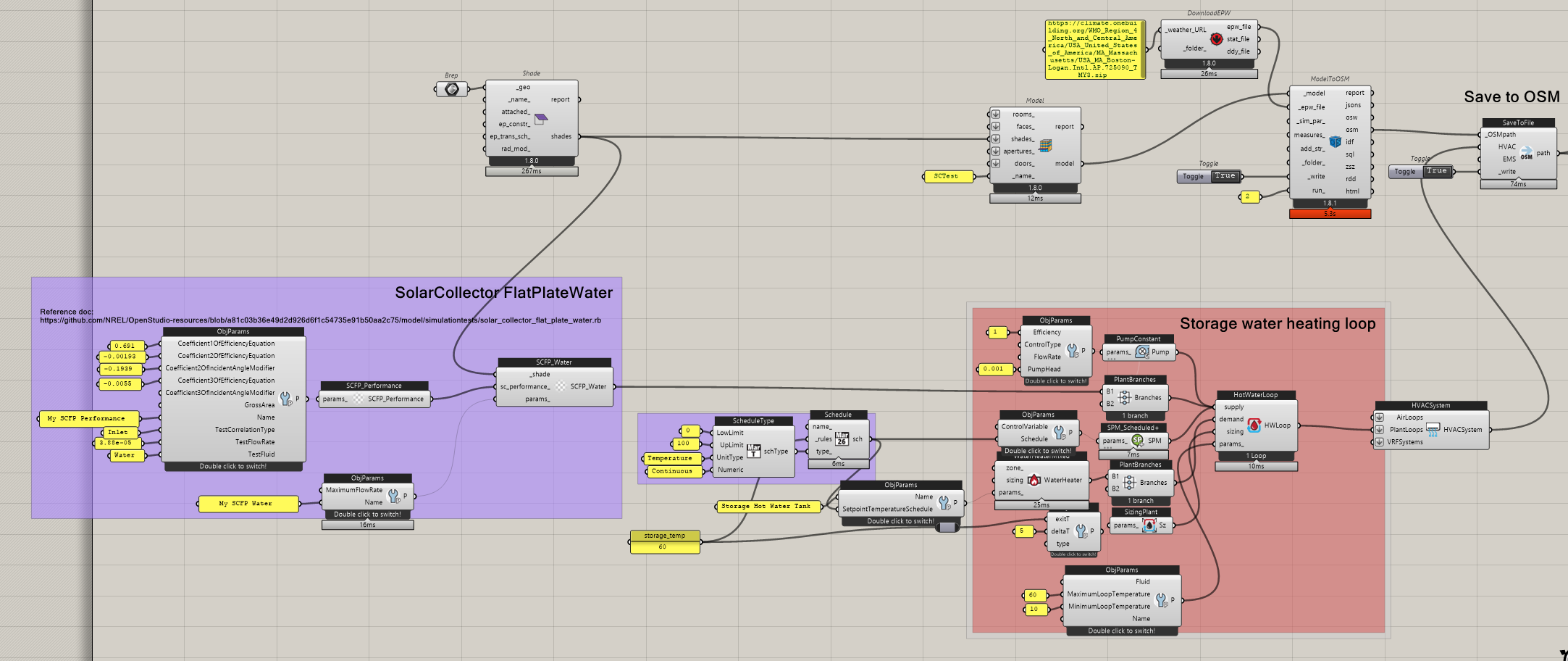
To use the solar collector, the entire 2 loop should exist, top loop and bottom loop: the top loop contains the solar collector as the supply and the tank as the demand, the bottom loop contains that tank as the supply and a baseboard as the demand
NOTE: this should align with a real HVAC system in the building to solve the heat balance. The example below is a simple idea how to use the solar collector in a building, in the building the HVAC used is a PTHP, which could be replace with your desired system. Find the example attached.
NOTE: the file is just an example, it is not calibrated and tested in realistic system, for your use, you need carefully design the house, the program, the setpoints, etc.
To run the below simulation, you need to set the units in the Rhino Canvas to meter, then in the Grasshopper, select all the components, right click, select Recompute, then select again right click and select Enable.
I didnt realise you could model the supply and demand side from the WaterHeater:Mixed component as it only had one output. Should have just tried it.
This will save a lot of time
Thanks again!
do you have any experience with the desiccantBalancedFlow? can you do the same thing with it attached to the OA stream and exhaust stream of the OA system?
I currently have it modeled as shown below but it is being written back to front in to the IDF with the regen inlet node set as the OA outboard node.
If you do not mind, let’s move to a new forum ticket, since this current ticket is for the Solar collector integration. Just to keep the forum sorted and clean.
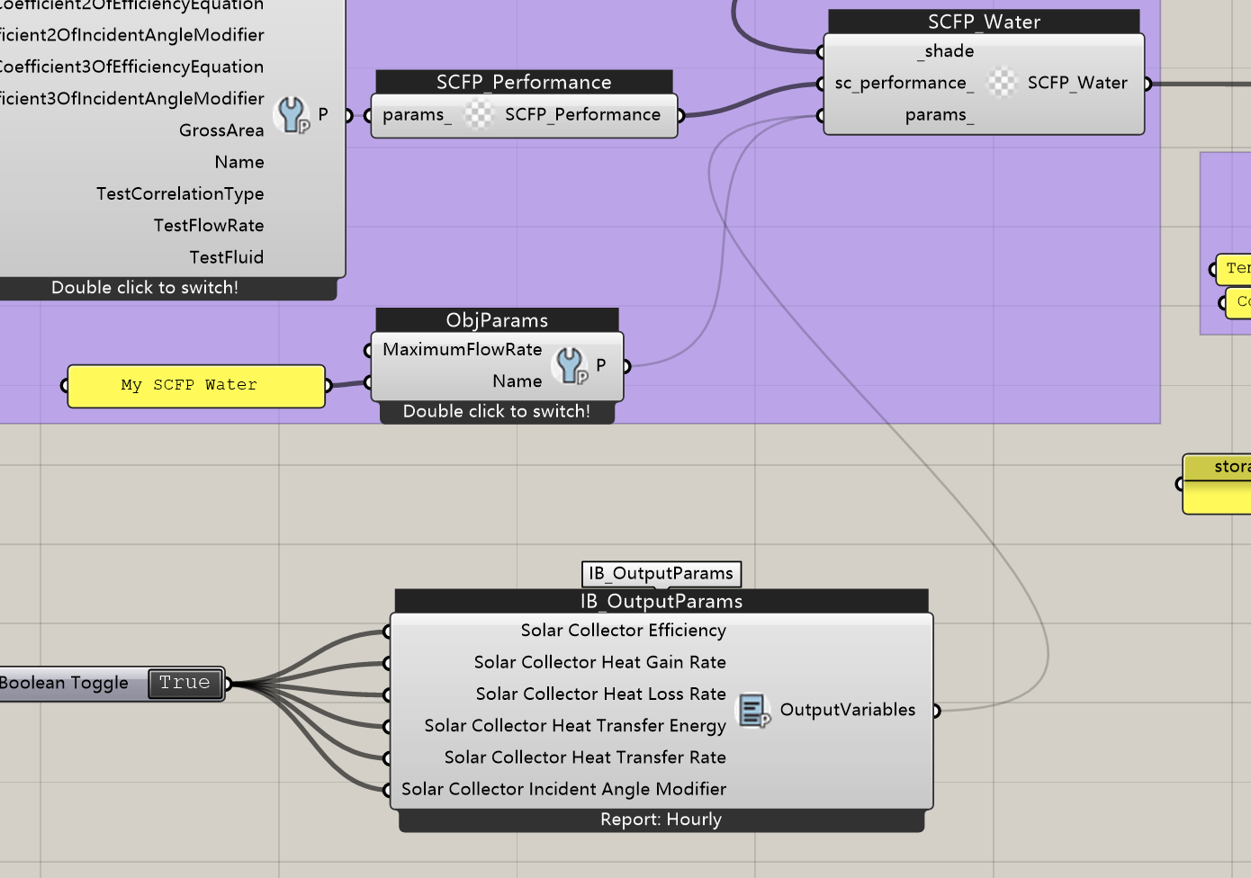
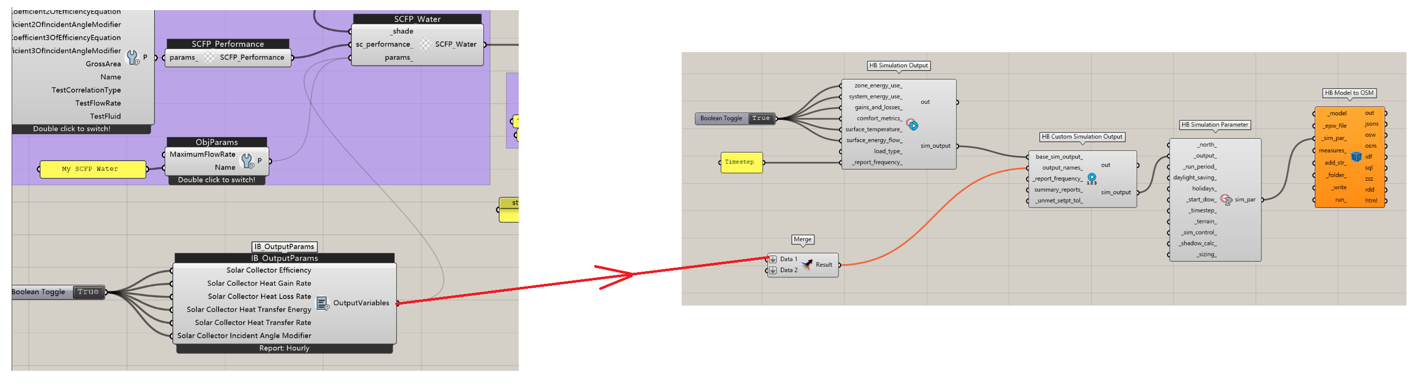
In Ironbug, I used IB_OutputParams to define several variables (e.g., Solar Collector Heat Transfer Energy) with the report frequency set to Hourly. I connected these to the custom SQL output, but after running the simulation, I couldn’t find corresponding values for these variables.
Could you please advise in which output file these results should appear, and how I can properly export them?
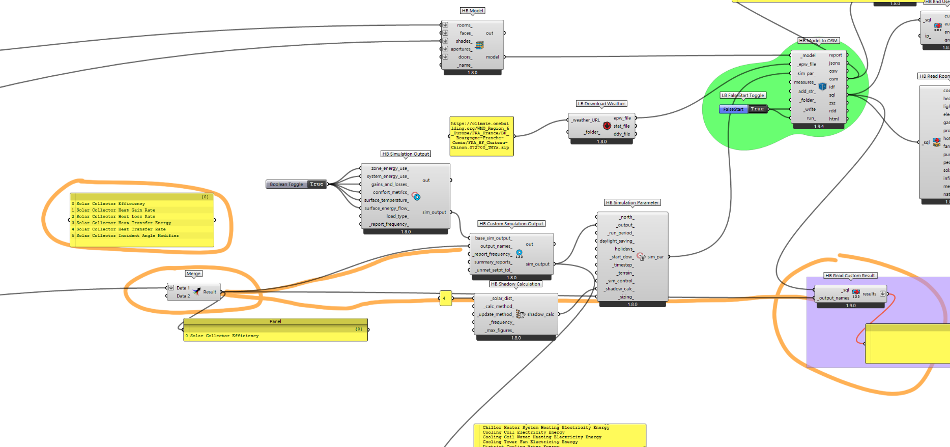
Thank you very much for your reply and guidance. I used the example model you shared earlier and tried using the Merge component, even directly writing the same result names in a panel. However, I still couldn’t find the corresponding results in the custom SQL output.
Please find attached a screenshot of my script below — it’s the same as your example model. Do you happen to know if there might be any other possible causes for this issue?