I am really stuck in a big problem and my time is limited to finish my simulation, would therefore appreciate any fast help/idea.
With my model one should be able to trigger the model from .csv files which performs a daylight simulation on a window with blinds. Additionally, the epw file plus the month, day, hour can be provided to achieve a different illuminance result on the geometry.
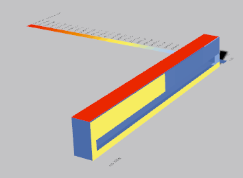
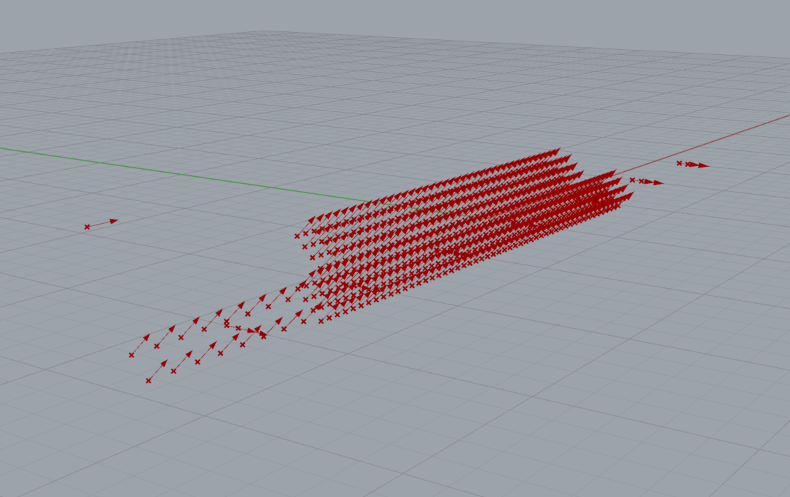
Now my problem is, that the west wall of the geometry isn’t changing it’s illuminance value at all even though I vary the sun’s position with the hour, day, month inputs. The result for a simulation at 5pm you can see attached. Not visible on the attached image is the east wall, which has quite a high illuminance level, god knows why, this is definitely not as I would have expected it. My model is also attached below to provide you with all the settings and configurations I have used. Don’t try to run it on your own; there are quite some .csv files which need to be provided to make it work running; sorry for the inconvenience.
To clear some doubt in advance: I am sure that my epw file is in the correct format and provides reasonable sunpaths - I looked into it with the sunPath component among others.
Still, I hope anybody had a related issue and could help me. Perhaps @mostapha can forward me if my issue is related to another.
I just answer to future visitors what I tried in the last hours (I really need this solution soon - that’s why I need to push this!!)
Rechecked all my connections and settings. Looked into RADIANCE rtrace parameters to see if there might be an issue and run the simulation also with qualities 1 (medium) and 2 (high) - nothing changed. Tried to play with the “north” property of the standardCIESky component, which resulted in a different illuminance analysis for the same hour, but still the west surface (and the back surfaces (all in direction of y+ axis)) are showing no illuminance increase… I also looked into sunCalc, i.e. how RADIANCE calculates the sun with a provided gensky command. Also no luck there to find a bottleneck which results in my messy picture.
NEW: Another thought I had is that I probably connect the several geometries and test surfaces in a wrong way - or I don’t apply a “flatten” of the data where I should. If somebody at least can give me a feedback on this one I would appreciate it very much.
If you have a physical ground plane in your model (which you should), that will reflect radiation on to the walls. Currently the only radiation seems to be the one incident from the sun and sky. The hemispherical ground definition in the sky file doesn’t usually contribute much to the scene.
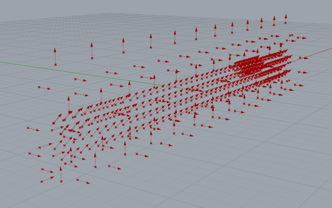
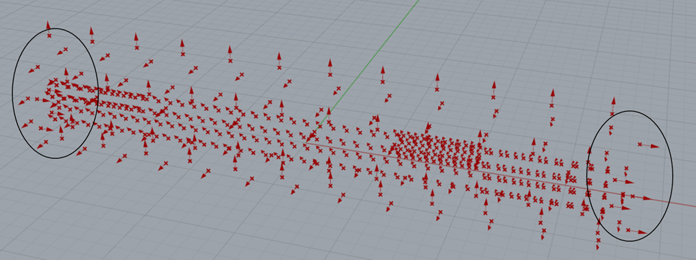
Is there a reason why the illuminance sensors in your model are facing in inclined vertical directions? Some of the illuminance vectors appear to be facing 45°.
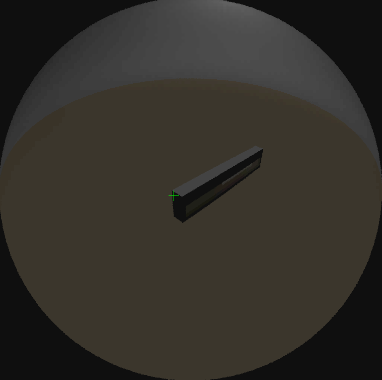
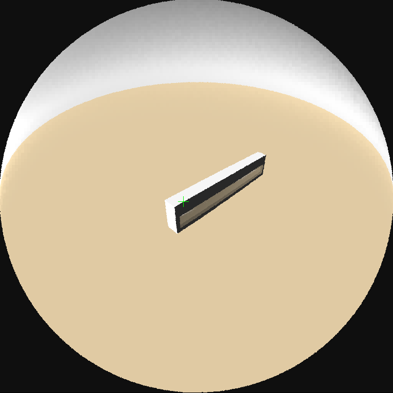
Your model appears to be okay. The west wall will be illuminated based on the sun position:
(Sky def in your folder: !gensky 5 6 16.0 +s -a 46.03 -o -8.9600000000000009 -m -30.0 | xform -rz 0.0)
Hi Sarith,
First of all: thank you very much for your fast help! This is really great!
Now to the points you mentioned:
Yes, this is intended. The window with blinds is intended to be in a high-rise building and as such ground reflection can be neglected. That’s why I didn’t add any.
I don’t really get to which illuminance sensors you are refering to. Do you mean the ptsVectors of the testmesh? My goal is to cover the whole geometry (including windows, blinds, etc.) with testmeshes to get Radiance results for each single surface.
Thank you for providing me with this mighty information - this is a big relieve. Looking at the images it seems to me as it would be already (almost) dark with the sky def in my folder; do you may know why or is this just due to my provided input of the epw data file?
The two pts files that you have in your folder have the vectors facing in the following directions. Its very unusual, even in empirical measurements to have illuminance sensors at inclined angles, unless you are measuring the radiation on a PV panel or such.
Right, yes they are inclined because the blind is tilted. Well, that’s what I think is the cause for the inclination, as the blinds are tilted by 45°. But this is not the reason for the non-illuminated west facade, am I right?
With the west facade I am still very confused why it has not a high illuminance value. Even when I set the hour to 8pm when it gets close to sunset, the east(!) facade has high illuminance while the west is still in dark blue (i.e. almost 0 lux). Do you may know what can be the cause of this? May it be due to the direction of the illuminance sensors you showed in the first picture?
Yes, I wasn’t considering blinds. Anyway, having blinds in your simulation will complicate things a bit. Try setting -ad to around 2048, -aa to 0.05 and -ar to 1024. This might result in the simulation taking a lot longer. Secondly, you need to increase the number of points on the walls. Right now you are tracing rays from very few points.
This might be because the illuminance sensors in one wall are facing inwards and the other wall are facing outwards. Shouldn’t they be both facing inwards (assuming that you are measuring illuminance inside the room)? Ideally, the sensors for vertical illuminance should be facing inwards and at a certain offset from the walls so that they dont get affected by shadows.
Thanks - I did change the setting and it resulted in a better resolution, but still the facade east-west issue
This definitely seems to be the cause of the problem! I wish them all to face outwards as I want to know the illuminance on each surface (I require these values in a thermal analysis with Matlab to see how the heat flow distributes from one side of the frame to the other).
Do you know how I am able to change the illuminance sensors? My way would be to hard-code some python code which checks for sensors facing in the wrong direction and correcting them. If you have a better idea I would welcome if you share it with me. Further, it would be great if you could provide me with the model you used to visualize the sensors; if you don’t mind (screenshot of the model would be fine).
Unfortunately I left for the day and won’t be able to get to those files till late evening tomorrow (CET) or the day after. Anyway, the code for visualizing the sensors was a quick hack using the native visualize vectors component in grasshopper. I wrote a Python script to parse through the pts file and redirect the sensor locations and directions to that component. The anchor point will be the location of the sensor and the vector will be the direction of the sensor (first three numbers and last three numbers respectively in each line of your pts file)
Regarding assigning the correct locations for illuminance sensors, you should be able to use the Honeybee component to do so. You might be able to find some examples with vertical illuminance on this forum where people have done so.
Thank you Sarith for your great support - I managed to solve my problem with your help. @mostapha thank you as well for looking into my question and providing the final piece which made the implementation of the changes easy.