Hi everyone,
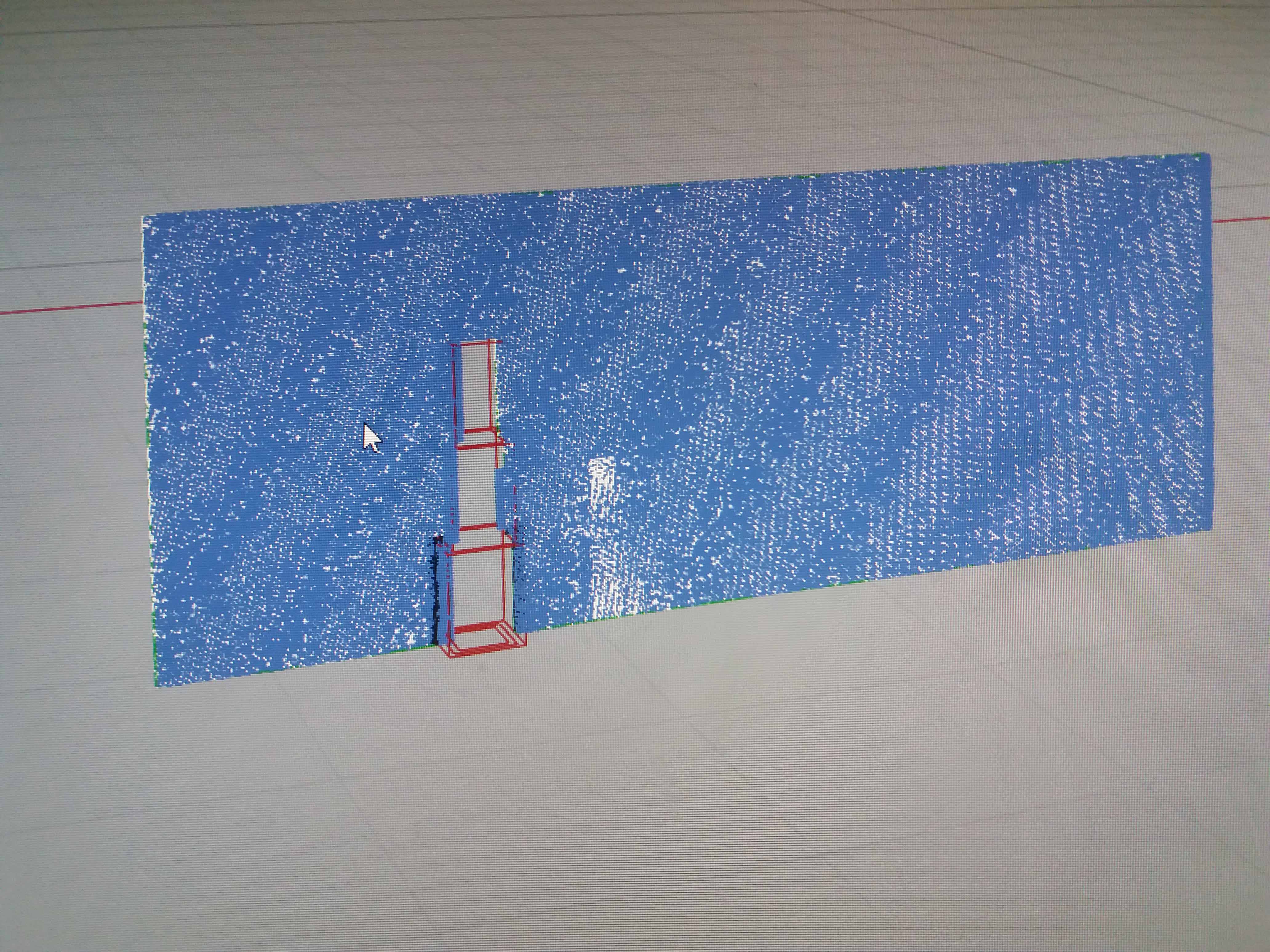
It’s a while that I have this kind of problem with BF results. As you see in the attached image all vectors appear as blue. I also conducted another test in which i put the test point surface somewhere that it did not have any intersection with the building geometry and it all gets correct. all coloured vectors appear.
I guess it may be a problem with my building geometry ( it is a closed polysurface).
any idea?!
hi @samira
It’s hard to tell without looking at your definition. Please share it and confirm that your rhino units were in meters.
Hi @OlivierDambron
Thankyou for your attention.
Here I put the definitions & yes the units is meters in all files.
1-Case1-1–test 7.gh (71.1 KB)
3-Case1-2–test 1.gh (75.3 KB)
Hi @samira
First I notice that your file contains old butterfly components. please make sure to have them updated and replaced.
Let us know how it goes.
This is how you can update butterfly to the latest version
Hi.
@OlivierDambron thanks alot to you. I updated butterfly succefully and with special thanks to @devang for the great instruction on updating it. It really helped me. Now Much of my problem with vectors is solved although still i have that problem with some of the horizontal analysis surfaces but i’ll try to fix it.
Now I have a new concern. Do you know if I can somehow get the drag coefficient of the building as a number from BF? I tried to find something relevant in previous discussions & all I get is that I think It’s kind of related to function object. Am I right? And How?!
Hi everyone.
Could you please answer me on this? I could use any advice from you
Thankyou
Samira
Hi @samira
You can calculate drag coefficients with an OF function object. It’s not yet developed in BF however, but you can find all the objects here (for example): https://www.openfoam.com/documentation/cpp-guide/html/guide-function-objects.html
I haven’t tried it myself yet so can’t help much at the moment. You can try and searching in the OF tutorials, you can also find those online, can look for drag in the github.
Kind regards,
Theodore.
Hi @TheodorosGalanos
Thank you for your advice. I actually don’t know much about scripting but i just tried to figure out something from what i read in OF & BF documentations. Now I gave  as the input of function objects component & everything seems to be ok. (Does this script seem reasonable to you?)
And It may be a silly question but i don’t know where to find the outputs( lift & drag quantities). I’ll appreciate any help from you.
Thankyou
Samira
forceCoeffs1
{
type forceCoeffs;
libs ("libforcesFunctionObjects.so");
log yes;
writeTofile yes;
patches (walls);
liftDir (0 1 0);
dragDir (-1 0 0);
pitchAxis (0 0 1);
magUInf 100;
lRef 3.5;
Aref 2.2;
}Looks good to me, one way to find out :slight_smile  Make sure the ‘walls’ is the actual name of the butterfly geometry or geometries you wish to calculate drag for.
The results should be saved in a postProcessing folder inside your case folder.
Kind regards,
Theodore.
Hi all,
This is a great thread, thanks everyone - your contributions have helped me a lot so far.
I am trying to replicate something similar to what @samira has done above - adding a force vector to the result. I would like to eventually visualize this vector as an arrow coming from the object in GH.
I have tracked down (I think) the updated link to the OF function objects documentation here and tried to follow, but being new to Butterfly my understanding is still a little patchy on how to integrate.
https://www.openfoam.com/documentation/guides/latest/doc/guide-fos-forces-forces.html
1 .I have not been able to see a result being saved in the postProcessing folder, just the standard P and U files.
2. And even if that did produce a result, I don’t really understand how to get the data back into Grasshopper. help!
First I tried the exact text that @samira used, and then i reaslied that some entries are mandatory and some are optional, and so I have been working with a simpler version. If I include “writeFields yes;” then the solution does not run, for example. But if I delete it, it runs but no output.
Please help me figure out what I have done wrong!
I have attached the definition - it’s a modified version of the outdoor airflow example with my own simple sphere geometry.
200531_Sphere.gh (441.1 KB)
Hello Nick,
did you manage to solve your problem?
Hi, no I have not solved it, If anyone knows the answer, that would be great!
200531_Sphere.gh was missing some information in the definition of functionobject. For incompressible flow, you need to define rho. It is written in line 80 of the following link.
https://cpp.openfoam.org/v5/forces_8H_source.html
So, for example, you need to add the following statement to functionobject.
rho    rhoInf;
rhoInf    1;
I don’t know of an easy way to load the output into grasshopper. It may be better to write the code yourself.
this function object seems to work for me:
forceCoeffs
{
type forceCoeffs;
libs (“libforces.so”);
pName p;
UName U;
rho rhoInf;
rhoInf 1.0;
log yes;
patches (your_patch);
liftDir (1 0 0);
dragDir (0 1 0);
pitchAxis (0 0 1);
CofR (0 0 0);
magUInf your_value;
lRef your_value;
Aref your_value;
}
be careful to adjust you lift, drag and pitch directions…
hi there,
@kinonotofu and @AEH96 - thanks a lot for your help. Just getting my head into this again after a bit of a break. I think I understand a bit better what’s going on with the control_dict.
I was able to get a result using ‘forces’, and able to get that info back into GH by reading the .dat file. Using ‘force coefficients’ (exact text above) caused the solver to fail for some reason. But forces works now, so just went with that, I couldn’t figure out what was different. It’s what i was looking for anyway. This page helped me with more detailed descriptions of each line: OpenFOAM: User Guide: Forces
I’ll attach my definition below in case it’s useful.
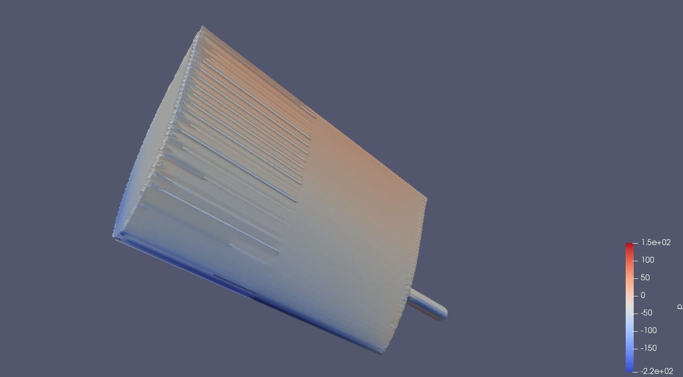
What I’m trying to do now is to get believable results. I modelled a wing, 2m x 1m, approx. NACA65012 section and cross checked it with a simple 2d analysis. I am expecting a Cl 1.2, Cd 0.0177, = lift force ~ 325N and drag of 5N. Not expecting it to quite hit these numbers due to the configuration / span, but should be somewhere in the ballpark?
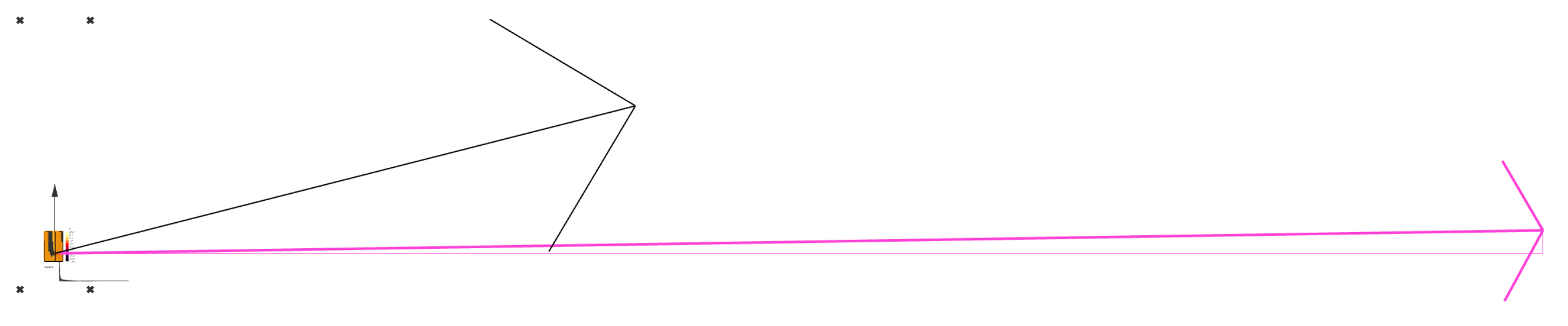
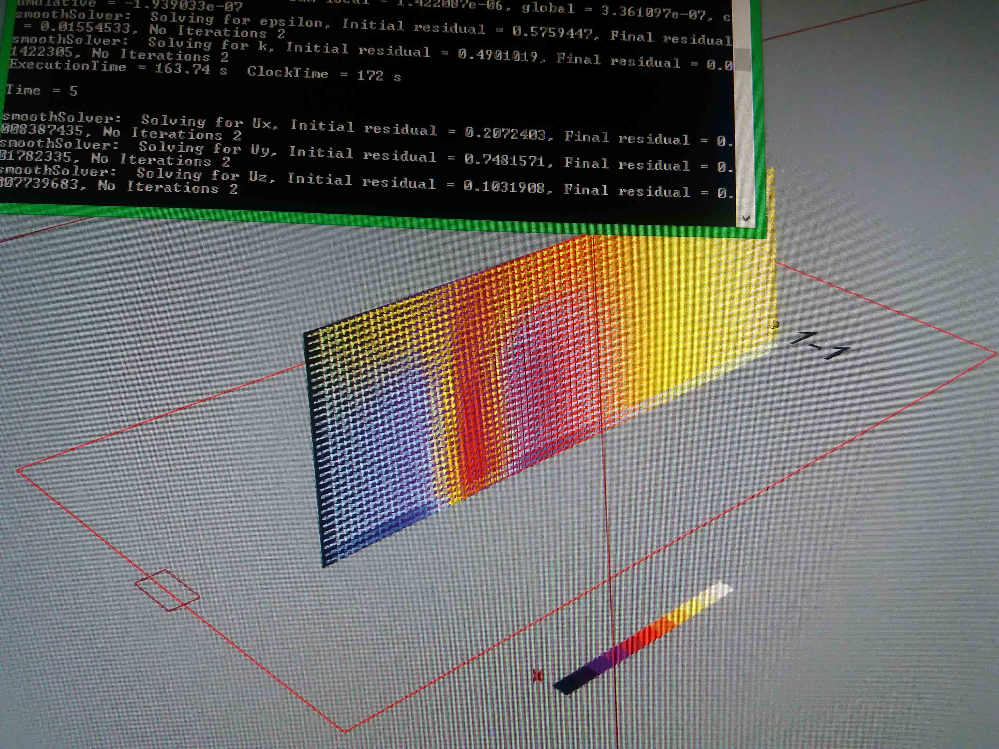
Calculated force vector (black) Expected force vector (pink) from 2D analysis
No of steps - 2000 (how do I know when enough? - Solution seemed pretty stable after 600 steps)
Time Interval - 0.000333 (approx. smallest cell (0.005m) / wind speed (15m/s))
Starting Mesh Cell size - 0.1 (i dont know, is this way too big? I wanted a relatively quick simulation)
thoughts:
- Sum of Pressure & Viscous force vectors is about 130N? Seems too low.
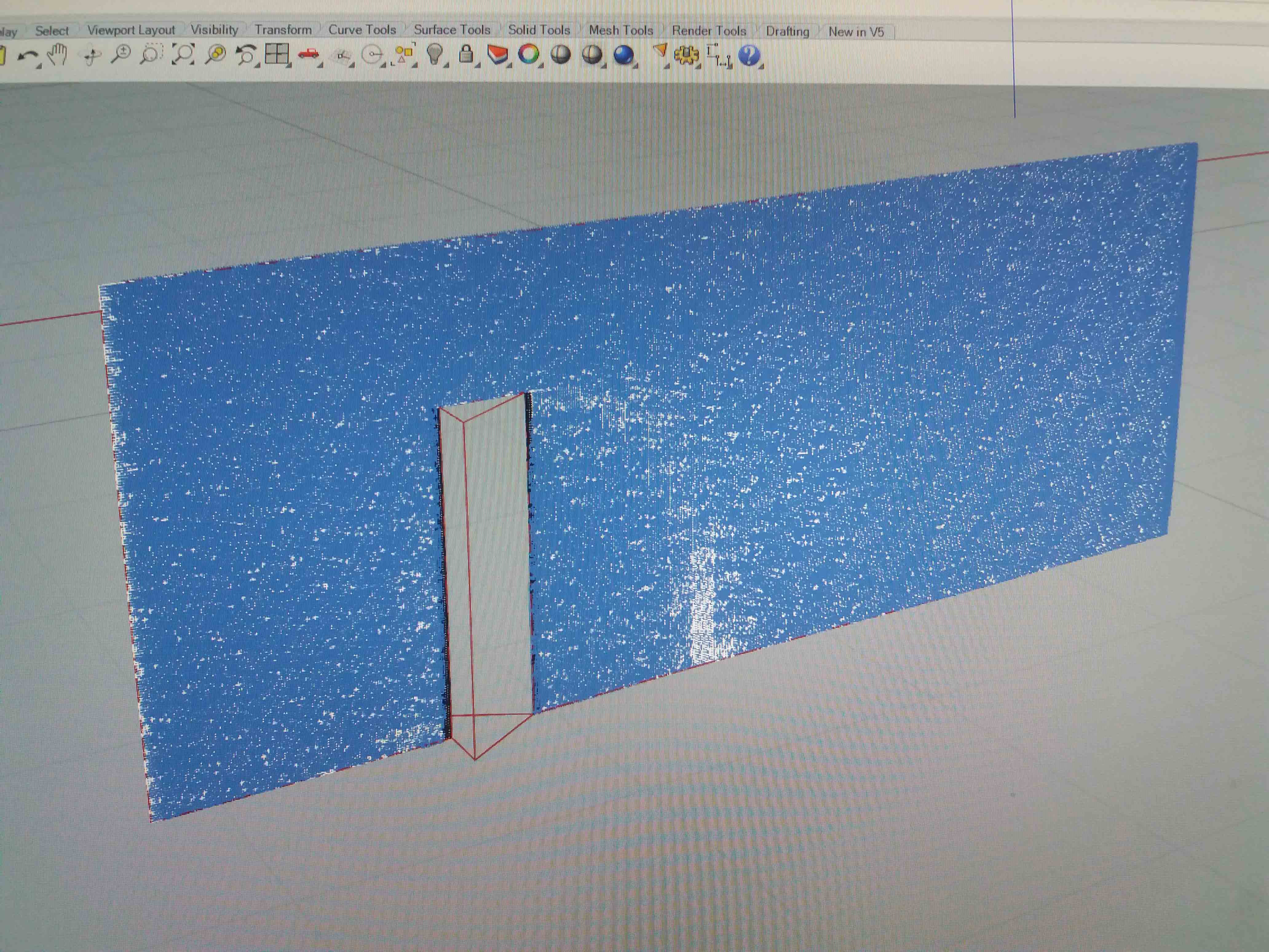
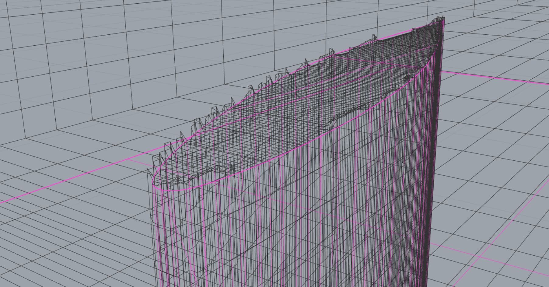
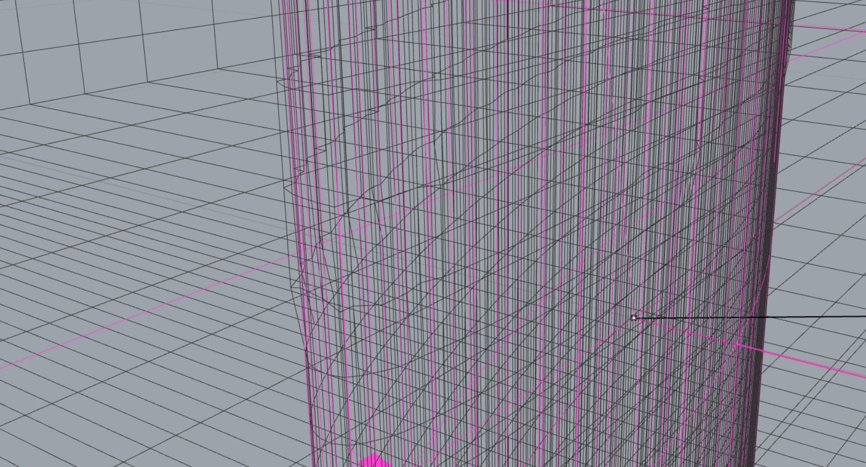
- Meshing looks like it has issues that I can’t figure out how to resolve - see attached. Ridges / bumps in the smooth surface. Assuming this affects the result?
- The file doesn’t run if the object doesn’t touch the side of the tunnel, hence adding the tube thing at the base of the wing. Should this be the case?
I know this is drifting off topic, but let me know if you have any further thoughts.
Nick
221016_Wing.3dm (223.9 KB)
221016_Wing.gh (452.9 KB)