Hi everyone !
I’m doing some studies in order to optimise PV installation on a selected surface. My aim is to represent the difference between three simulation :
The first one considered the surface 100% covered by PV module which have the same tilt and azimuth as the selected surface.
For the second one user can select the percentage of the surface used for PV modules. Here, the tilt and the azimuth are again the same as the surface selected, and the surface of PV Module is generated.
The third one works as the second one, except it used tilt and azimuth optimised.
At the beginning I did not find correct result because the surface generated with the PV System Size tool was bigger than the surface selected. I think I found my mistake, and try to input “systemsize” from the PhotovoltaiqueSurface tool to the System Size tool, and use the Surface generated to input it on the second PhotovoltaiqueSurface tool in order to calculate the AC energy per year. At this Moment I found some consistent results because the surface generated considered the percentage, and the power of the third simulation was bigger than the second one.
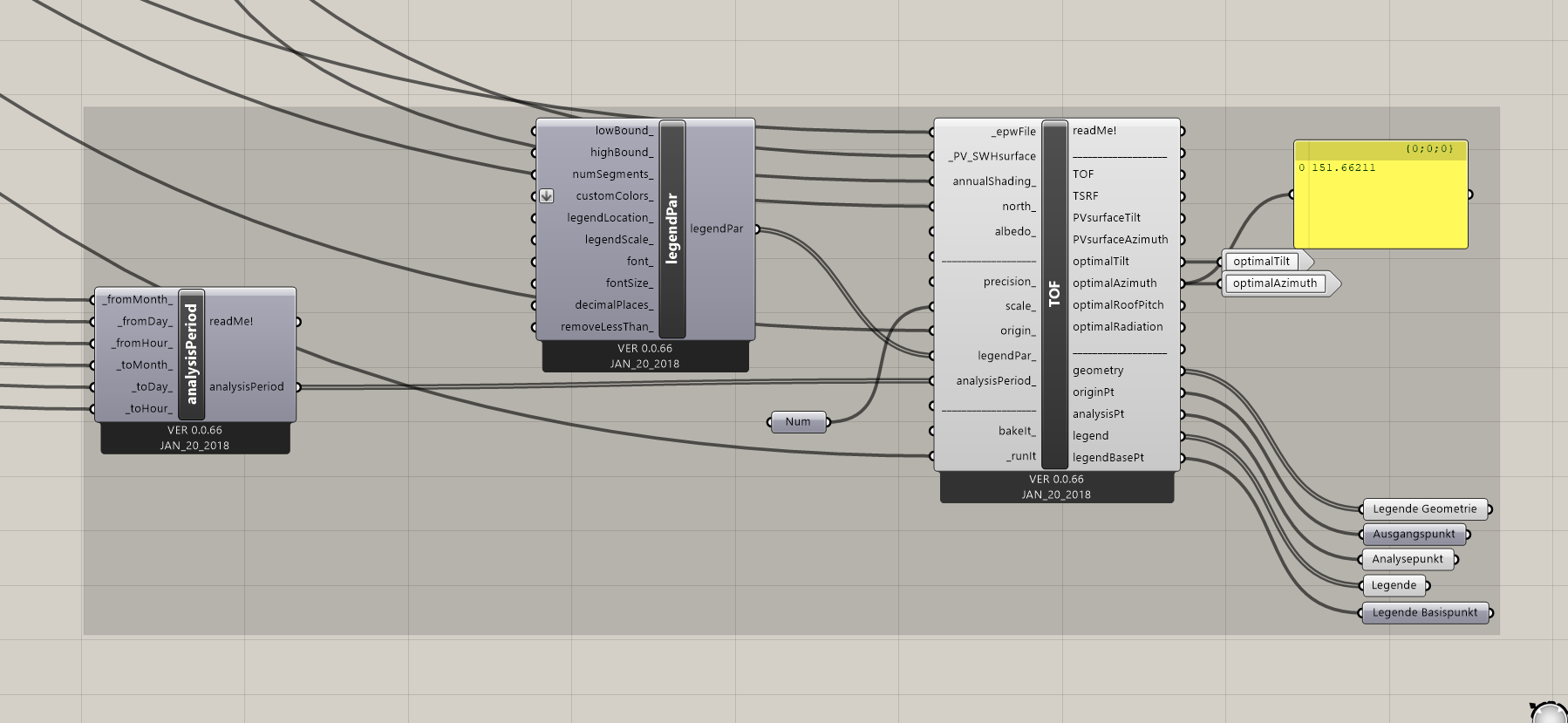
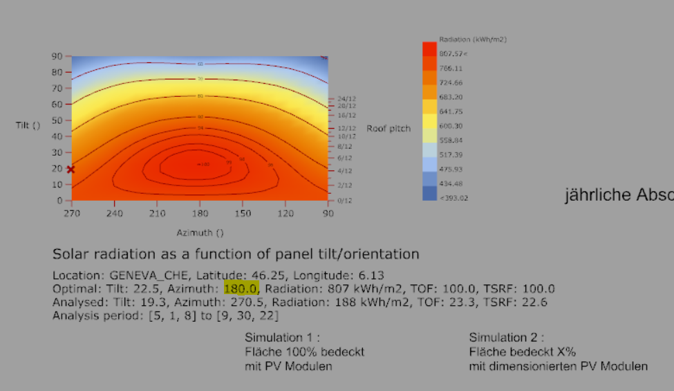
Now begin problems. I decided to do some Cluster to clear the grasshopper model and for the next guy who will used this Programm. I wished to checked a second time when it was finished, and for several examples, my results were not in compliance. Indeed, the second simuation gave me hicher results than the third one. And the azimuth optimised, written on the TOF Schema, did not match to the value the third simulation used (c.f pictures)
Everyone had already this kind of problem ? Cluster break correct link between Tools ? It sounds strange but it is the only solution I found. I hope someone can gives me a clue to resolve this problem. I know it is more complicated for you dear users to help me without the file, but the company doesn’t want this file on the Internet for confidentiality reasons.
Any suggestion are welcomed, thank you very much ! 
Ben
I tried again with the value of 180 for optimal azimuth and it works. But I still do not understand why the value of Optimal Azimuth isn’t 180 but 151 after the tool …
@djordje, your thoughts on this?
I normaly found the “error”. TOF schema give the optimise tilt and azimuth according to it reference : it’s normal, 180° matches to the south where we have the optimal solar gain. On the TOF tool we have the optimal azimuth matches with the south in the 3D model referential ! So to find the correct value imputed to the Surface tool I used a slider for the optimal azimuth and search the best angle which gave the best AC Energy results. Finding this correct value, I used If conditions and the values to calculate exactly the optimal azimuth in the correct referential. And it worked for each case !! Tomorrow I’ll give the convert tool for any one 
So as I said before you can find the Demonstration in the file attached :
NEW REFERENTIAL DEMONSTRATION.gh (117.4 KB)
Best Regards
Hi @benjamin.grouteau ,
Please accept my apology for taking me too long to reply.
If I understood correctly you are suggesting that there is a bug with the “optimalAzimuth” output of the “Tilt and Orientation Factor” component?
I downloaded the .gh file that you attached, but the surface is missing.
Can you please internalize it?
If you are not allowed to upload the entire brep geometry, you can upload just the part of it, on which you performed the analysis:
Thank you in advance, and sorry for the late reply once again.
It’s not really a “bug”, just the geometry referential which is not the same as the ladybug referential. I attached again the .gh file with the Rhino file used. I tested the programm with many Surfaces, and it worked every time.
Thank you for your reply !
180709_NEW REFERENTIAL DEMONSTRATION.gh (563.2 KB)
180709_Forum model.3dm (599.5 KB)
Hi @benjamin.grouteau,
Thank you for attaching your files.
What would be the ‘referential’? The north_ input?
Hi @djordje !
I attached a Schema to illustrate my explanations
We have a top vue of a the model, the gray surface is the one selected. The blue referential is the refenretial of Rhino, according to the axis. In orange we have the North of the project, and in green the normal of the surface selected. When I used TOF tool, the angle of the azimuth written on the Rhino Scene was mostly 180° but in fatcs it depends of the time Analysis. So we are agree that it’s the angle from the North to the South. But the Output value of the TOF tool on grasshopper isn’t the same, and when I was using it as an Input I didn’t find the best amount of energy. That’s why I tried with a slider several values for the azimuth optimisation, and the best angle I always found was the d angle (why I don’t really know). The a angle is given by the TOF tool because it’s the optimized azimuth angle of the surface selected in the Rhino referential, as the c angle representing the azimuth of the surface selected. I used both of them to find the d angle.
Thank you for your attention
Hi @benjamin.grouteau,
Thank you once again for the patience and the screenshot.
So the “referential of Rhino” is basically Rhino’s coordinate axes: x and y. Or did I misunderstand you?
Sorry for being picky once again, it’s just I am trying to understand your terminology on this.
Yes that’s it ! No problem it’s me, I didn’t explain very well sorry
Hi @benjamin.grouteau,
Indeed, I see the issue now. Thank you for noticing and reporting the bug!
I am at the moment working on something, but I the bug will definitively be fixed in the up coming period.
You can use your fix up until now.
Once again sorry for the inconveniences, and thank you for reporting it, and fixing it!