@djordje , As all panels are typical in shape and area, I conduct annual shading only for one panel, is this right?
Hi @RadwaEzzat ,
I am not sure I understood you. Do you have the latest .3dm and .gh files?
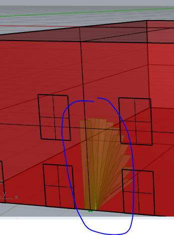
Yes Mr @djordje, I attached files, assuming that there are 6 pv panels mounted on building south facade as one system, as you can see in rhino file, and i want to calculate energy output of these panels as one system. you can see my first question in a pink panel in the attached file. My second question is as you can see in picture, the pv surface output from " system size" component, which I use in “pv surface component to calculate energ, different from the actual pv panel mounted on facade. I mean different in shape although it is the same area, but i think the differnt shape effect energy results specially when calculate annual shading. I understand that is because of using the " system size” component, which i only because this is the only way used to define tilt and azimuth angles of PV panels, so that i asked you previously about any another way to define tilt and azimuth angles of PV panels without using " system size" component. I hope i explain my problem better and I hope you can help me with the solution as you always do.
My third question is that I had three months rhino version but it expired yesterday, then the programe stop working and i cannot reinstall rhino with different email to take another free 3 months, so i installed version out of official website, and then i notice that the programme (Grasshopper and LB, not rhino) become very slow, do you have solution?
2022.05.13.gh (459.7 KB)
2022.05.13 v6.3dm (85.9 KB)
Hi @RadwaEzzat ,
Check the attached files.
2022.05.14.gh (430.7 KB)
2022.05.14 v6.3dm (70.8 KB)
Have you ever used Grasshopper before starting to work on this Photovoltaics project?
I would recommend making your .gh file a bit more tidy, cleaner.
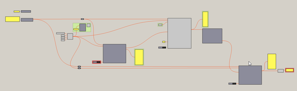
You should remove all the unnecessary components, inputs. Make sure that components are a bit aligned in between themselves, where possible. Try making the wires in way that they don’t look like spaghetti (intertwined). Take a look at how I made my .gh file:
Here you can find example how to align components.
When I said that wires should not look like spaghetti, I meant making them horizontal, and also using relays.
Untidy .gh files can often discourage another person from helping you.
I would suggest asking about this on discourse.mcneel.com forum.
Yes Mr @djordje you are right, this project is the first chance for me to use these programse, so I am beginner, but I will take your advice in consideration in the next files, many thanks.
Regarding your attached file, I understand what you do but what you do is in the fixed PV condition. As I say I want to calculate energy of these 6 panels mounted on south facade in different four conditions (fixed, H-axis tracking, V-axis tracking and dual axis tracking. So could you please help me.
Hi @RadwaEzzat ,
Knowing Grasshopper is essential to working with Grasshopper plugins (like Ladybug). It is obvious why.
Also some parts of the .gh definition which you may see in Ladybug Photovoltaics files, often have nothing to do with Ladybug Photovoltais components themselves, but are just regular everyday Grasshopper components, and their concepts.
Typical example is Mass Addition component.
You can also find ‘Sort’ component, ‘Range’, ‘Flip Matrix’ and plenty of other regular Grasshopper components. If you are not familiar with them, this makes your work and my work difficult.
Grasshopper and its tools are powerful software, but not a magic stick to get automatic results for a certain task.
Second issue I see is that:
Your project raises a lot of questions: how will the substructure look like? Your last screenshot shows a H-axis tilted panel which is clashing with the facade wall.
How will you determine the spacing between dual axis tracking panels? Ladybug has no such capabilities.
If you are making dual axis tracking panels, then shading from other neighboring panels is not an acceptable principle. At least not acceptable during the analysis period you are interested (summer? whole year?) and certain time period (9-15h, whole day?).
Your question is basically a separate project. You can make a research from it. It is not something that someone can help you with in 10 minutes of their time on internet.
I would advise the following:
-
Grasshopper
Learn Grasshopper basics. You can choose any tutorial/book from here. -
Ladybug Photovoltaics
Through our discussion, you already learned the basics of Ladybug Photovoltaics:
-
check the normal vector direction of input PVsurface.
-
define module settings (with the use of ‘Simplified photovoltaics module’) component. There are more advanced version of this component (CEC and Sandia) in case you have specific module from actual manufacturer, and not a generic one.
-
define losses (with the use of ‘DC to AC derate factor’) component
-
how to get system size from input surface. That’s this custom python component:
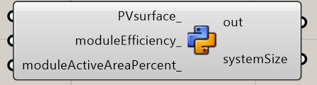
-
perform non shaded analysis
-
perform shaded analysis
If something is unclear, check the example files. There’s a description there above each component, which may help you understand why we use those components.
One thing that missing is how to calculate optimal tilt and azimuth angles of an array. This can be done with the use of ‘TOF’ component. You can see its usage in the gh file below.
I attached an example of a south facing 6 panels, grouped into a single array. For the south facing facade, you don’t need shading from the building behind it, as such shading losses are negligible.
And example includes comparison between:
- fixed tilt/azimuth, with optimal tilt angle
- H-axis tracking with 180 degrees azimuth
- V-axis tracking with optimal tilt angle
If you want to have these 6 panels separated, I leave this to you. You would have to find out how to space them in a way, that they are not shading one each other.
If you want dual axis tracking variant, I leave this to you as well. Open the .gh file and try understanding how it work. H-axis and V-axis are created based on regular Grasshopper components principle - sort each hourly kWh output, take the largest value, sum all the largest values. The key to making this variant is dealing with Grasshopper tree data matching. You should learn that concept first.
I believe you will figure it out. All the best with your project!
2022.05.14b.gh (490.9 KB)
2022.05.14b v6.3dm (55.0 KB)
Yes Mr @djordje, you are right. all these questions you talk about are already took in consedration in my project. When I send any file to you to help me I just send a simple example to describe my question but the geometry and pv panels mounted on it in the way you see in files is not my real case study, so I would like to thank you for your efforts in helping me to understand every detail in project. Regarding the .gh file you attached 2022.05.14b.gh I understand all what you do perfectly and it i sooo helpful. Only One step I want you to add in your attached example is that what component should be connected to “sunpath shading” component . To be specific, assuming that you will take annual shading in consedration (I mean you will connect "dc to ac derate f " component, even if in your south facade example file (I know that shading losses are negligible but I only want to understand the correct inputs should be connected to this “sunpath shading” component (in case of if i want to put panels in other facade directions no in the south). Thanks alot and I will wait for your updated .gh file.