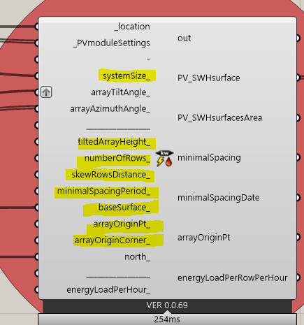
Hi, I am working on project to define energy amount poduced from PV panels mounted on building facade in 4 different ststus (fixed, H-axis tracking, V-axis tracking and dual axis tracking), I used (PV system size) component to define PV surface, but I need a help in defining inputs in this component correctly (showed in figure below) according to my study case of PV position on building facade (showed in attached rhino file in drive link). I wish some one can help me as I am beginner… Thanks in advance
Hi @RadwaEzzat ,
Sorry that I saw this topic too late.
If you hover over any Ladybug component’s input or output, you will get a description of it. Here is an example for the systemSize_ input:
systemSize: DC (Direct current) power rating of the photovoltaic array (on one of your facade faces) in kilowatts (kW) at standard test conditions (STC).
I made a small example which would make it more understandable what each of the inputs you marked does.
With exception of minimalSpacingPeriod_. I would not change that input, and let the component itself calculate it internally.
You can play around with inputs in the .gh file below just to see how they are affecting the creation of PV_SWHsurface output.
I hope this helps.
Can you attach a .gh file where that increase from 0.35m2 to 0.37m2 happens?
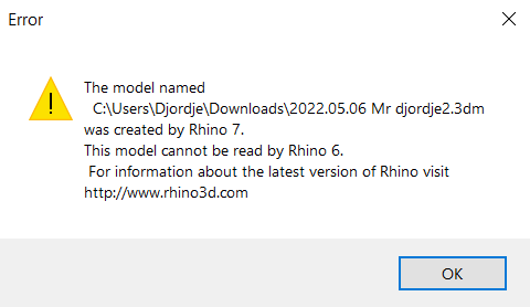
And if you can save the .3dm files in the Rhino 6 file format please (File->Save As->Rhino 6 3D Models), because I don’t have Rhino 7. Thank you.
Mr @djordje, here the attached files, as you see I try to make horisontal axis tracking using tilt angles from 0 to 90 with fixed azmuith angle 180, assuming that a pv panel with 0.35 m2 actual area mounted on the south facade of the showed building in rino file (sorry I upload it firstly in v. 7 but now I edit it to version 6). As you can see using pv system size component change area to 0.37 although i try to make horisontal axis tracking using another way without using PV system size component as showed in gh file and it does not change the area… 2022.05.06 Mr djordje2 v.6.3dm (61.3 KB) 2022.05.06 Mr djordje 2.gh (422.3 KB)
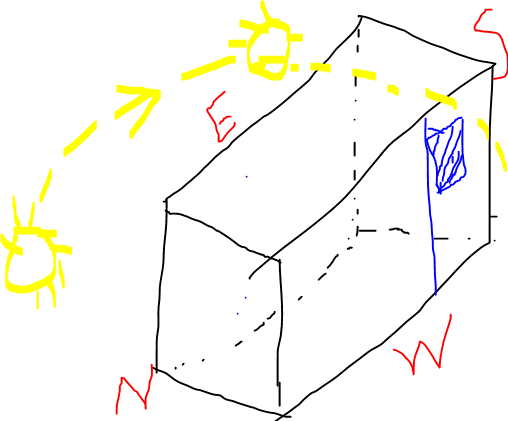
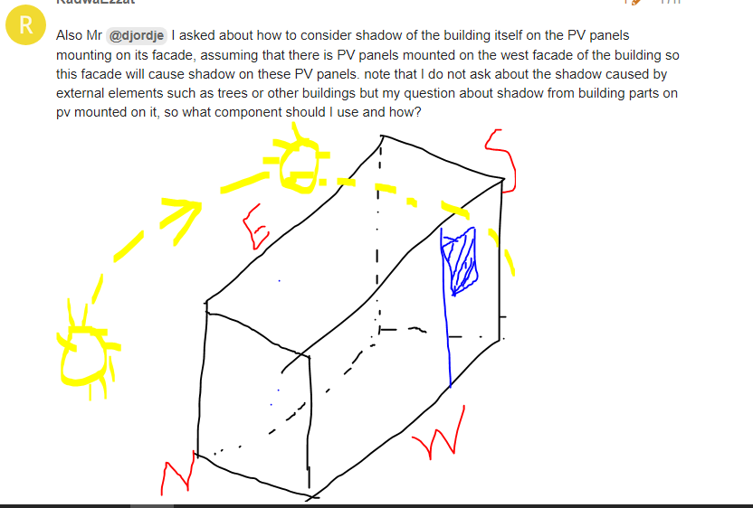
Also Mr @djordje I asked about how to consider shadow of the building itself on the PV panels mounting on its facade, assuming that there is PV panels mounted on the west facade of the building so this facade will cause shadow on these PV panels. note that I do not ask about the shadow caused by external elements such as trees or other buildings but my question about shadow from building parts on pv mounted on it, so what component should I use and how?
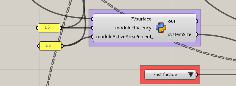
The reason fro 0.35 to 0.37m2 difference was because not all inputs were the same. Once you define ‘PVmoduleSettings’ you should have those same data inputted in every other Ladybug Photovoltaics component where you see the ‘PVmoduleSettings_’ input.
Second problem was that systemSyze step was 0.01kW in this custom component:
I increased it to 0.0001kW. So now you get 0.35m2.
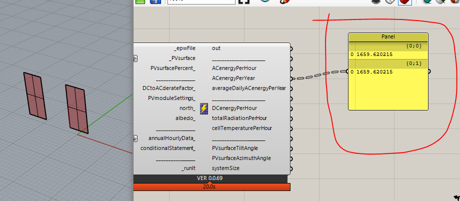
As for your self PV panel shading, check the red colored list box in the picture above. It will enable you to switch from East, South, West facades. I don’t recommend putting PV modules on the northern facade.
Mr @djordje, I hope you see this question, I just still did not understand how to consider shadow of the building itself on the PV panels mounting on its facade (for example, as illustrated in attached picture, assuming that I want to get energy output of the pv panel mounted on west facade, how to consider the effect of west facade shadow on pv panel mounted on it . As I know that annual shading equal zero by default. I hope you also help me in this too.
Hi @RadwaEzzat ,
It is useful to check Ladybug Photovoltaics example files number 019 and 020, in order to understand how to account for shading.
Basically you first need to perform unshaded analysis, then get annual shading, and then again perform the analysis with this annual shading value to get the final - shaded analysis results.
@djordje, If there are more than pv panel mounted on facade (foe example 4 panels in one column), then I get energy output value for each panel separetly, but I want to get the result to be for all these panels (as they are considered as a one system on building facade) what should I use to do that??
Hi @RadwaEzzat ,
You can account for losses in-between panels with ‘DC to AC derate factor’ component’s ‘wiring_’ and ‘connections_’ inputs.
However, both of these already have default values (2% and 0.5%) defined by NREL (Ladybug Photovoltaics is based on their model).
If you have an array consisting of tens and tens of panels, then you can slightly increase the ‘wiring_’ input. The question is by how much?
NREL website states that upper 2% value is reasonable for most systems. So I would not change it.
Essentially because ‘wiring_’ has default value which is not 0% - this means that your ‘_PVsurface’ input for the ‘Photovoltaics surface’ component is not a single panel, but an array.
Mr @djordje, Seems I couldn’t explain my question.In another words, I ask about these values showed in picture, assuming that we need results about energy output of these two panels “one value” as they are in one system, not two values as shown. how to get the result to be for all these panels (as they are considered as a one system on building facade) what should I use to do that "to get energy output one value ?
Mr @djordje , when I apply simulation on my case study ( There are many separated pv panels mounted on building facade), the simulation take very long time specifically in case of dual axis tracking simulation. Is this any way to reduce simulation time or make it faster? Thanks
Also, I want to ask if there is any way to use LB v.0.61? even if I use older version of rhino?
I would not recommend. Or you can use it, but then I can not help you if you have any questions, because as mentioned it may be that LB v.061 has bugs since it is from 2015.
As for the taking too much calculation time: shading calculation can take significantly longer.
Is each of your PV panels analysed for annual shading?