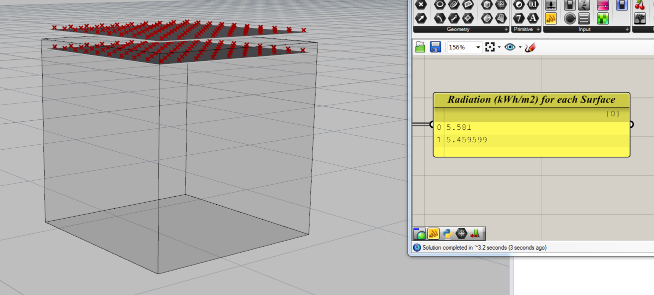
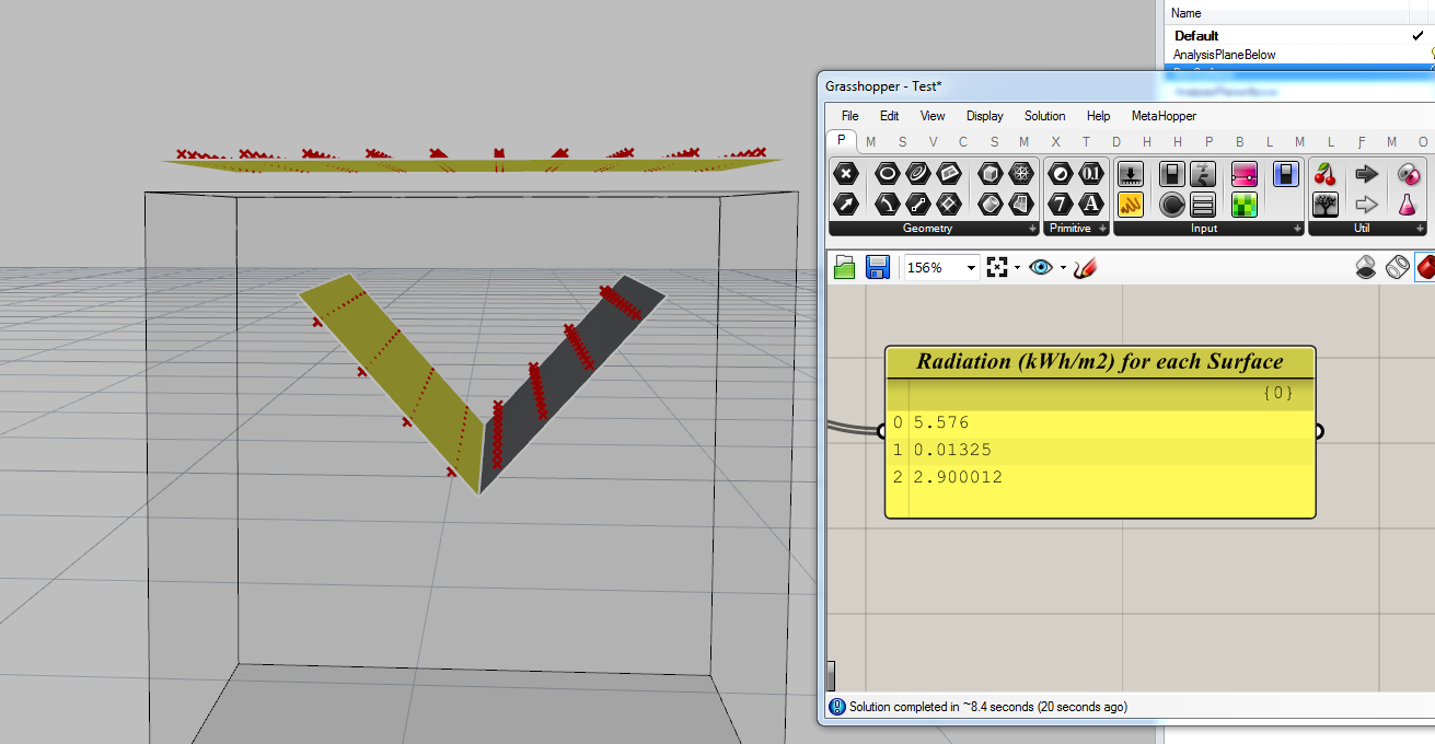
I was comparing performance of glass vs trans materials and come across a rather unusual phenomenon. For my test case I used a simple box with lid at the top as glass/trans material. I placed my analysis planes above and below the glass surface to define the analysis points. I defined rest of the box surfaces with a Reflectance of 0.01 to minimize any internal reflections.
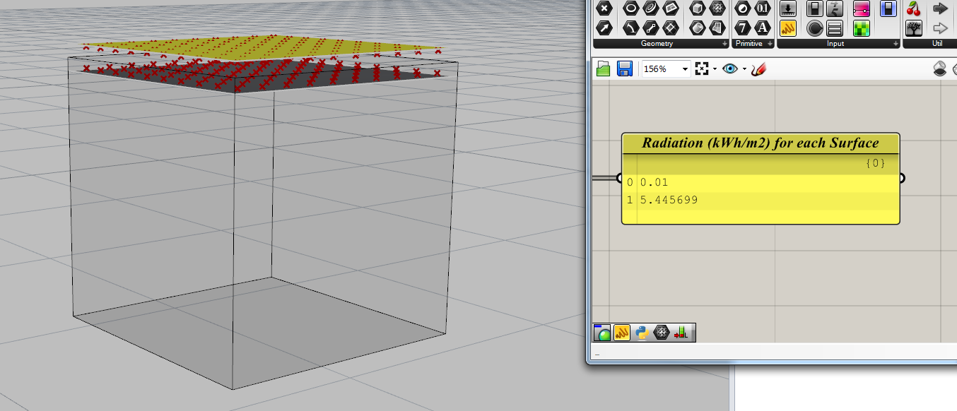
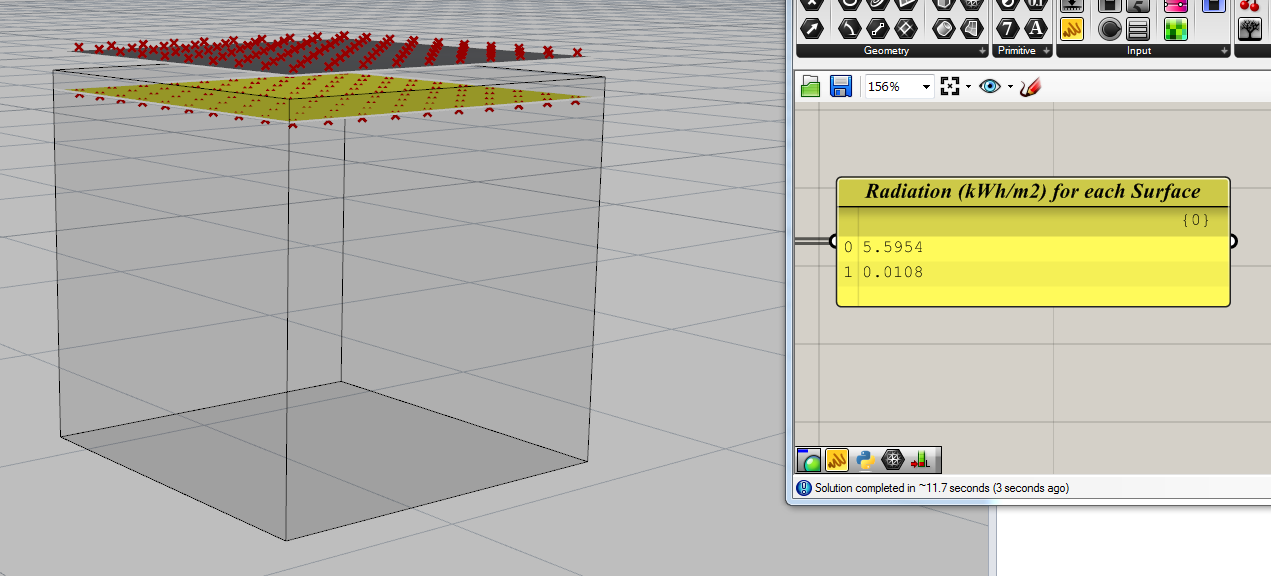
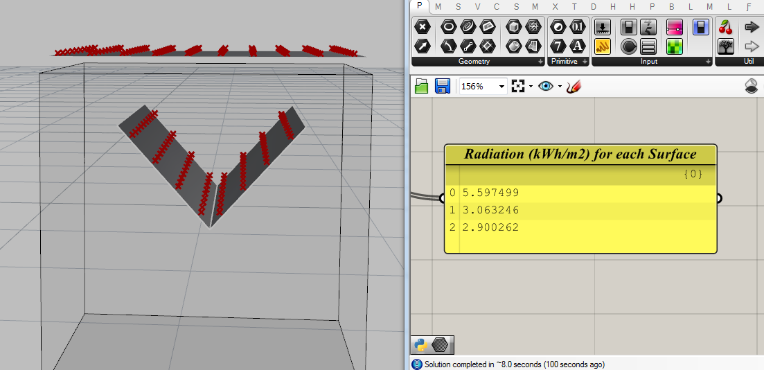
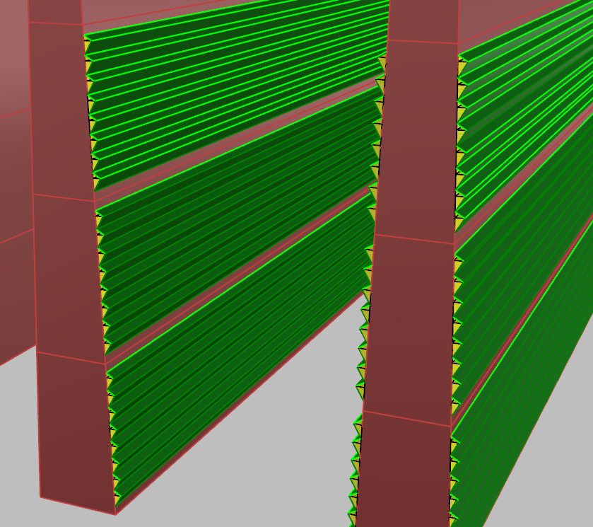
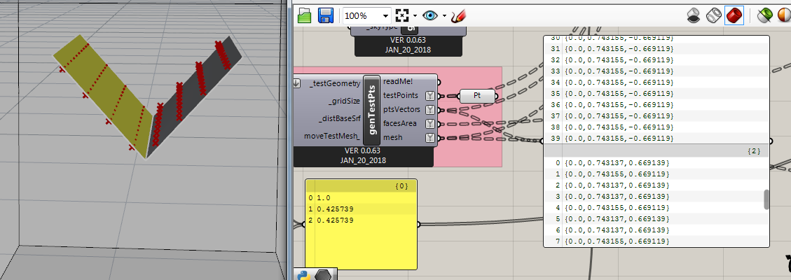
It seems that the analysis points are affected by the normal direction of the analysis surface. However I am very sure the analysis planes themselves are not part of the simulation. For the test case mentioned below I have removed the glass surface as it doesn’t really play any role. Pls refer to the below images to see what I mean. Yellow colour represents backface.
I also tried simulating hourly daylight, same phenomenon. I changed different scales - meter, millimeter, changed dist from base surface, grid size, etc. same!
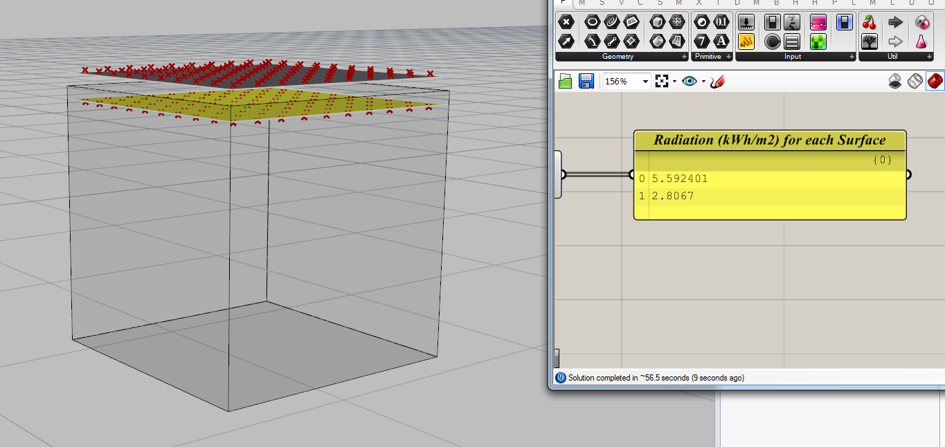
Additionally, if I change the box interior surface reflectance from 0.01 to say 0.5 (or something significant), depending on the no. of bounces I DO get the reflected values recorded on the analysis points.
If I have correctly understood what you are doing , the results that you are getting are to be expected. Irradiance measured by Radiance is the raw radiation results sans the photopic efficiency calculations. Unless you are doing measurements inside an integrating sphere, the illuminance/irradiance value will be affected by the cosine of the angle between the illuminant and the directional normal (https://mysite.du.edu/~jcalvert/optics/lumens.htm). In your case, the illuminant is the celestial hemisphere (sky) which subtends a solid angle of 2pi. So, if you tilt the calc plane, your results will be different.
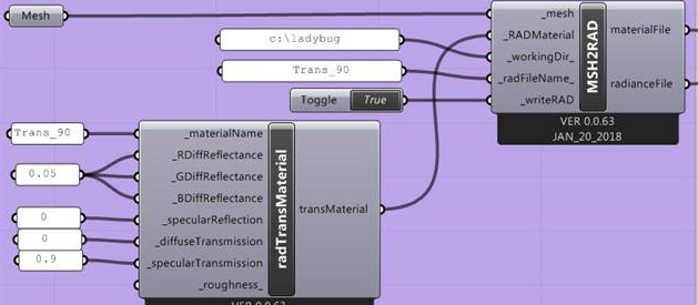
By the way, trans material is somewhat of an amalgamation of plastic and “nothing” (radsite.lbl.gov/radiance/refer/usman2.pdf). It’s also notoriously hard to get right. So, based on the trans material parameters, the grid below it might receive a lot less radiation.
Thanks for the reply and the information. I briefly went through the links you sent. I can understand how the calculation is done for a hemisphere decided by the surface normal and not as a sphere. Tilting the calc plane changes the hemisphere and now I can understand what you meant.
This makes me question the way I understood setting up analysis points in space. If I have an analysis plane floating horizontally in a room lets say, I would expect the analysis points to capture the radiation/illuminance from all directions. I wasn’t expecting it to be dependent on the surface normal of the analysis plane. If not taken into account this would significantly change the results. As in the 2 pictures above, I would have expected about the same results on the \ / planes.
As for the trans material, there is no glass/trans material involved in the results I have posted.
My aim was to capture photons received by plants on a vertical wall. I decided to use a transparent material representing my plants and place my analysis points behind the glass/trans material to calculate total radiation absorbed.
As pointed out in this discussion, using glass is ‘materially’ incorrect as it would have different reflection properties. Also, running some tests I found out that a 0.9 reflectance glass with 100 unit incident radiation transmited only 86 units whereas a trans material with 0.9 specular reflection passed 89-90 units.
Now that I am aware, I will take care in future about my analysis surface normals. However I am not sure if everyone using honeybee for daylight/radiation simulations is aware of it. It can lead to significant change in the results. I don’t know if it is something that can be taken care of in future or that’s the way radiance works.
So if I want to capture radiation from all directions, keeping dist from analysis surface as 0, I should simply add a copy of my analysis points and flip their normals.
Hi Saket, are you sure that the normals for the photosensors are getting tilted along with the planes from which they are derived? I assume even when you are tilting the planes the normals for the photosensors are still pointing upwards. That’s why you are not seeing difference. The “ray input” in radiance is based on position and vector direction. In the points file, which you should be able to find in the project directory, the ray inputs are defined in the format pt.x pt.y pt.z dir.x dir.y dir.z (where the inputs with pt indicate the position of the photosensor in world coordinates and inputs with dir indicate the orientation of the vector).
With regards to change in results due to scaling the model, if you scale the entire model you will not be seeing a difference in radiation levels (this won’t apply in case you have electric lights or bsdfs with proxy geometry).
I am curious to see what is going on “under the hood”… I don’t have a Rhino installation on my machine. Can you share the project folder with the Radiance files here?
Blockquote
So if I want to capture radiation from all directions, keeping dist from analysis surface as 0, I should simply add a copy of my analysis points and flip their normals."
Hi @SaketSarupria@sarith I have this question too! Do you have an answer now? I was trying to find the answer in the forum then I found this post in 2 years ago.
Hi @tiffiena, its been a while so I went through the thread again. My understanding is that the analysis point vector determines the hemisphere from which the rays will be captured. if you want both sides, duplicate your analysis points and flip their normals.
Is there any specific problem you are trying to solve?
Hi @SaketSarupria, thank you for your reply!
Actually I’m trying to calculate the irradiance/illuminance coming from all the directions falling onto a infinitesimal sphere… similar to Mean Spherical Illuminance. I found out that this value is not equal to the sum of results from two sides of the plane. I create a new discussion in the forum and it seems like not many people did this. I found the code in RADIANCE forum and still tried to see how I could apply this in honeybee.
If you are interested in that, here is the code: https://discourse.radiance-online.org/t/spherical-sensor/2651/4
I guess I didn’t follow up on this thread after Saket’s last comment in April 2018. So, belated apologies to him! I guess the discussion is stuck (or has progressed to) wherever Saket left it.