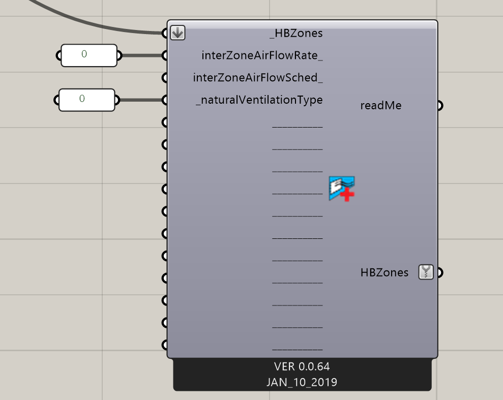
I´m working on a big energy model with a large space subdivided in numerous thermal zones, which are interconnected by “virtual interior windows” to allow airflow between zones - because of the complex zoning, I´m using the Airflow Network to model cross ventilation, leaving those “internal windows” always open.
The issue comes when I try to run comfort maps on the model, when using the Indoor View Factor Calculator. As I´ve used internal windows instead of Air walls, I cannot remove them from the calculation, and they are accounted for in the resulting mean radiant temperature.
I´d like to believe there is a way of making the Indoor View Factor Calculator ignore these internal windows, in a similar way to how it ignores Airwalls. So far I´ve found the relevant area of the code, but I don´t see the way to implement it.
Hopefully @chris or someone else can put some light on this, or any potential workaround.
The solution that I would recommend is likely going to depend on the specific setup of your model and whether you need the interior windows models as windows in order to let solar gain through them. If you don’t need to account for shortwave solar transfer across these virtual walls, I would recommend modeling these interior windows as air walls and using the Set EP Airflow component to set the air mixing between zones across air walls to be 0:
Then you can add your AFN using additionalStrings_ or whatever workflow you are using to add it. This should enable easy removal of the air walls in the comfort map temperature calculations.
If you really do need them modeled as interior windows in order to model transfer of solar gain across them, I might recommend doing away with the zone boundary altogether and just modeling the two connected spaces as one continuous zone. Remember that both air walls and interior windows will block the long wave radiant transfer of heat across them in E+ and direct sun passing across an interior window in E+ results in all of that shortwave solar energy becoming diffuse. Given that this is how E+ calculation deals with these situations, your MRT is probably not going to be that much more accurate by accounting for the surface temperatures on the other side of the interior window or air wall given that those surface temperatures themselves are not so accurate (having not correctly accounted for radiant heat transfer). So, for a case like this, modeling connected spaces as one zone is better.
Lastly, if these interior windows are relatively small openings, which is sounds like they might be if you have need of the AFN, the error that you will get from simply using the interior window’s MRT is likely not that large since the view factor to these windows is small. In a case like this, maybe it is best to just leave the calculation using the interior window temperature.
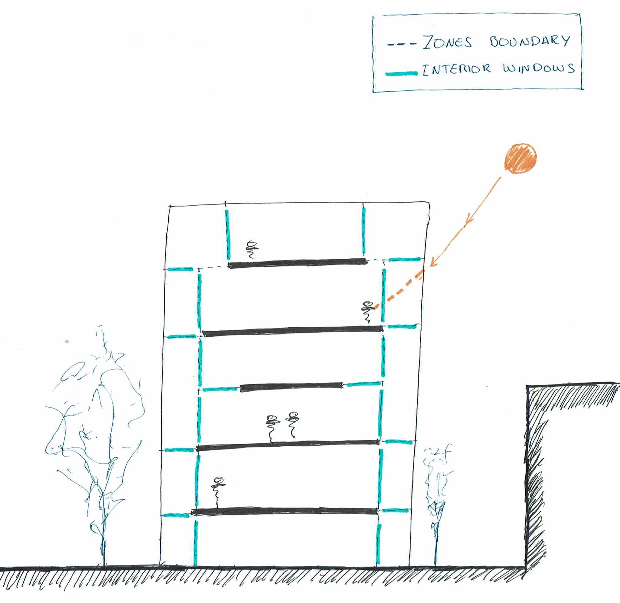
Unfortunately, the whole space is a big volume with several floors (with different uses) connected here and there so I can´t combine it all together. Probably I didn´t make it clear enough on my first post, a picture is always worth a thousand words.
The envelope is completely transparent, and therefore accounting for shortwave solar radiation in the occupied zones was the reason to go for the Interior Windows route. Not only that, to have a correct interior solar distribution the model was set with all non-convex zones - which added some extra subdivisions.
I´m aware that shortwave solar radiation becomes diffuse in E+ when it reaches the second zone (the surface temperatures of the second zone will not be perfectly accurate, but should be ok) and I was relying on the Solar calculation in the Comfort Maps to account for the direct impact of the sun on the people there. So far, I had done something similar in the past to vary the solar Transmitance of the windows when they are open, manually replacing the Internal Window Transmissivity output from Read EPSurface (original value when windows are closed, 1 when open), before connecting it to the comfort recipe.
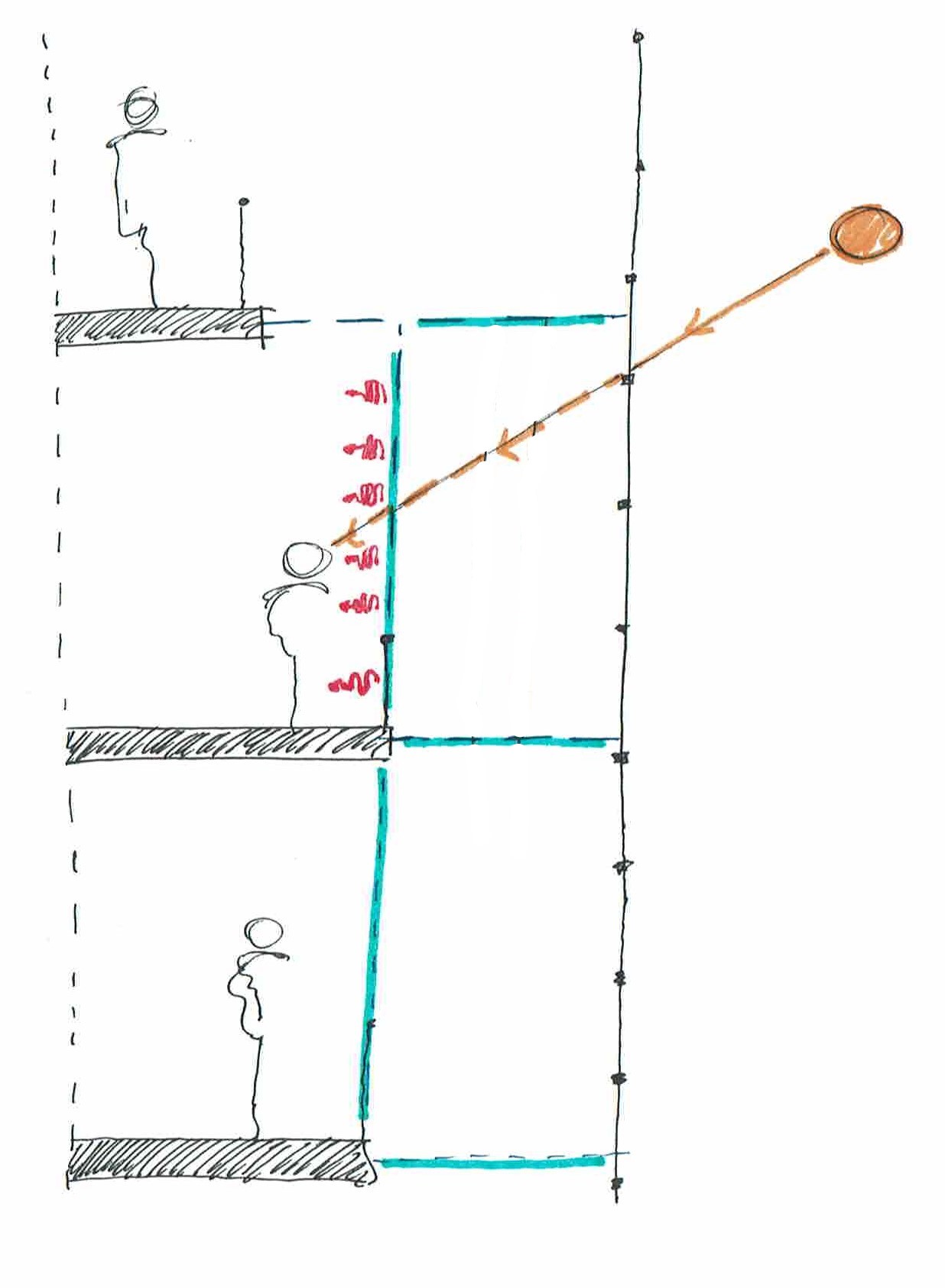
Unfortunately, in this particular case, as the sun reaches the interior window directly in the exterior zone I believe its temperature will excesively affect the MRT in the perimeter areas of the occupied zones.
I´m aware this is an extremely specfic case. The aim behind producing the comfort maps is to define the adequate shading for the envelope, not only for energy consumption, but to control the effect of direct sun on the users comfort inside.
The images definitely help and I agree that this is not a case for air walls.
Just to clarify: all of these “interior windows” represent completely non-existent boundaries in the real building, correct? If so, I was just thinking that maybe you could try boosting the transmittance of the windowmaterials here up to 1. In that case, they shouldn’t absorb any of the shortwave solar and so their temperature shouldn’t be affected by the absorption of shortwave solar. They will still be block long wave heat transfer but, for this, it shouldn’t make much of a difference whether one sees the interior window temperature or the surface temperatures on the other side of the window since they are probably pretty close to one another.
Another option (if these windows don’t actually exist in reality) is just to move them further away from the building perimeter such that you accurately capture all of the dynamics near the facade separately from the core.
Exactly @chris, the interior-windows are completely non-existing boundaries in the building.
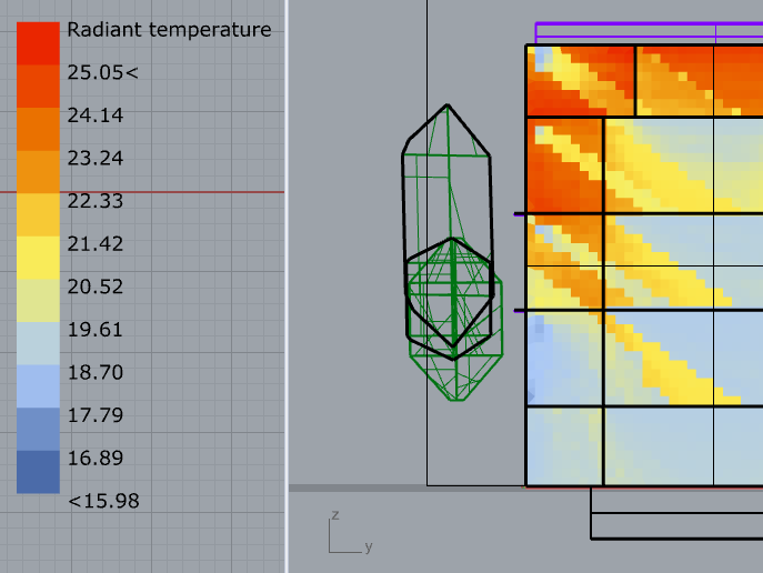
I´ve gone down the route you suggest, (boosting the solar transmittance of these interior windows to 1) and I think it´s working pretty well. The boundaries between zones are still noticeable, but it somehow makes sense since the floor slabs separating the internal zones are also colder.
@RafaelA ,
Glad that it is working out and sorry for the late response. One thing that I can recommend to have less of a jump with the floor temperatures is breaking up the floor into multiple surfaces so that the variation in floor temperature across the zone can be captured. You can see that this practice is used in this microclimate map example: http://hydrashare.github.io/hydra/viewer?owner=chriswmackey&fork=hydra_2&id=Comfort_Autonomy&slide=1
I would also just generally recommend breaking up large surfaces when building microclimate maps in order to make them more accurate.
I´ll definitely keep it in mind. I didn´t dare to break down the surfaces too much in this case, due to the size of the model. It shouldn´t be an issue if done carefully.