Hi all,
I am trying to model a simple thing but yet hard to find in honeybee HVAC details. The idea is to have a simple mechanical ventilation that blows outside air into a zone, with the normal ventilation rate (7 l/s/pers for example), and to add only a water coil cooler to this air to that the ventilation air is blown into the room for example at 18°C.
This is not classic air conditionning as there are no target zone temperature. The idea is only to cool the ventilation air in order to cool the zones a little (in my example, if outside air is already below 18°C, then the water coil cooler does nothing). The ventilation air does not follow a loop but rather a straight line : gets in the rooftop unit, gets cooled, gets to the zone, and is ejected from the zone.
This solution is quit common in France, I don’t know for the rest of the world. Has anyone any idea how to set up something like this with honeybee ?
Hi @Vincent
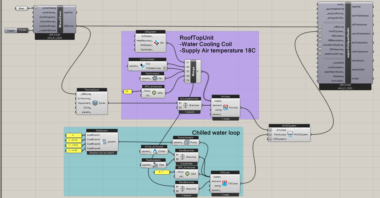
Your system can also have an air loop, it is just a single zone air loop if this helps you understand better.
Based on my understanding, here is what I would do for this system:
20200204_RTU_CW.gh (540.8 KB)
Hi @MingboPeng
Thanks for you quick reply. I implemented this in an already existing room model, and the results seem reasonable (Cooler room temperature than an unconditionned zone, and lower cooling consumption than a fully conditionned zone with set points).
Although I have a few questions : I went into the in.csv file after the simulation, I saw a lot of system air nodes in there.
Is there a way to know precisely which node number corresponds to which node in the system ?
I tried to find the node corresponding to the zone air inlet (i.e. the air hat is supposed to be blown at 18°C or outside air temperature if lower, at the mechanical ventilation rate) but could not find it. I found air nodes with a volume flow rate corresponding to what I had specified in my zone for mechanical ventilation (correct flow rate during occupation and 0 when unoccupied), but with air temperature similar to outside temperature or zone temperature. I also found air nodes that seemed to be corresponding to the air zone inlet in terms of temperature (outside temp or 18°C) but they had a constant flow rate all the time, a little over twice the required mechanical flow rate. Do you have any idea why is that ?
When using Ironbug components, all temperature setpoints schedule and airflow schedule that are set in the honeybee zone through components like “setEPZoneSchedule” and “setEPZoneThresholds” will apply to the HVAC system ?
Cheers,
Vincent
@MingboPeng
Thanks for the tip about naming air nodes, that’s really handy.
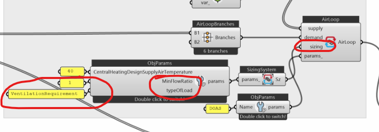
I tried to set the sizing of the air loop to VentilationRequirement, but the simulation gave really high temperatures…
There’s somethig I don’t understand, if all settings done with honeybee settings are not taken into account in the Ironbug components, where can we set up for example a cooling/heating temperature setpoint schedule for the zone, or a ventilation rate schedule ? Or any other parameter about the zone needs ?
I saw on Hydra (http://hydrashare.github.io/hydra/viewer?owner=MingboPeng&fork=hydra&id=Ironbug_Add_Schedules&slide=0&scale=1&offset=0,0) you gave an example for setting a ventilation sechedule through zone equipment parameters. But I still don’t get how we would set up a zone zones temperatures setpoint schedule. These schedule shoud influence how the HVAC system works, weather it’s able to meet them or not…
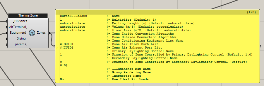
The ThermalZone component of Ironbug, that is connected to the demand side of the HVAC loop, gives only these information to Ironbug components? (i.e. mostly dimensions and algorithm) :
@Vincent
It is expected to see high indoor air temperature, when the system only takes care of ventilation requirement, and there is no additional cooling system.
As I said, Honeybee and Ironbug address different part of energy model. Ironbug only deals with whatever related to HVAC system, all Honeybee settings will not be overridden or not counted.
The example you found from hydra for setting up Ironbug schedule, that is setting air flow rate for air terminal, this the outlet of HVAC, which distributes conditioned air to zones. You are right, these settings only affect how HVAC behaves, not the zone.
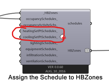
For setting zone setpoint schedules, here is an example: http://hydrashare.github.io/hydra/viewer?owner=chriswmackey&fork=hydra_2&id=Creating_Custom_Schedules&slide=0&scale=5.278031643091584&offset=-2113.6935558356777,-1794.7050214752683
Correct, the thermalZone component are mostly for HVAC sizing. You can check its Sizing_ input if you want to customize it.
-Mingbo