Solar Radiation Results - Section and Plan don´t match

Hi all,

I´m running into a problem matching the results for a Radiation Analysis in plan with those from two vertical planes. For some reason, even if the test points of the ground are offset to exactly match those in the first row of the sections, the results vary significantly.

I assumed that adding the Radiation Results for both directions of each vertical plane would give very similar results to the ground, but somehow this is not the case. I´ve tested it with two different EPWs and still the problem persists.

Does someone have any ideas on what could be causing this?

Solar_Radiation_Section.gh (506.7 KB)

The vector direction between the two are different. You need to match the vectors to get the same results.

Thanks Mostapaha. I see, I’ll give it a shot and post back here.

So far I´ve found my way around this by deconstructing the vertical mesh and rotating each face individually. However, for that to work, each face is simulated individually otherwise they obstruct each other.

With those results, I´m recoloring the orginal mesh and everything matchs well now.

This is fine for a few hundred points, but is far from optimal for larger cases. The Radiation Analysis is run once per point which ends up taking a while or even crashing sometimes. I´m still hoping to find a better workflow without going into Honeybee+Radiance for this, as Ladybug is pretty quick to set up and run.

Is there any way to avoid considering the geometry input as an obstruction?
It could be quite handy for some cases where the simulation is run for a virtual plane/section instead of a facade or ground.

@RafaelA here’s something we could try:

For each surface in your original, vertical plane analysis, extract the:

  • unit surface normal vector = surf_normal
  • unit radiation vectors = radiation_vec (all that hit surface)
  • original radiation value (scalar) = radiation_original

Then for each:
radiation_new = [(radiation_original) / dot_product(surf_normal, radiation_vec)] * [dot_product((0,0,1), radiation_vec))]

This basically assumes that the radiation on a surface is just the projection of the radiation vector onto surface area. So reverse that calculation to get the original radiation, and redo it with a vector pointing up (0,0,1) to get the amount projected onto a hypothetical vertically-oriented surface.

Currently at work, but I can give it a shot with your gh script if I get some time today.

S

Update 1: I took a look at the script and think there’s an obstacle that makes this a lot harder. In order to do the calc I suggested, we need all the sky patch vectors for every point, and unfortunately, I’m not sure which component provides that data.

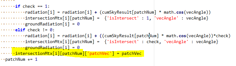
Update 2: Alright, I gave in and resorted to python to figure this out. The solution is a bit hacky, I modified the intersectionMtx output to include the sky patch vectors, and then revised the Real Time Radiation results component to implement my formula.
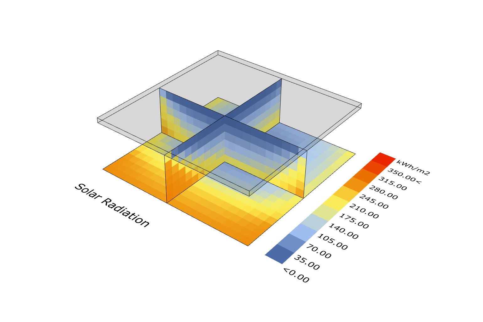
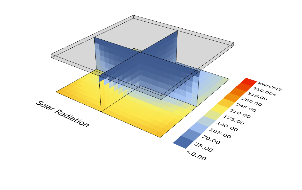
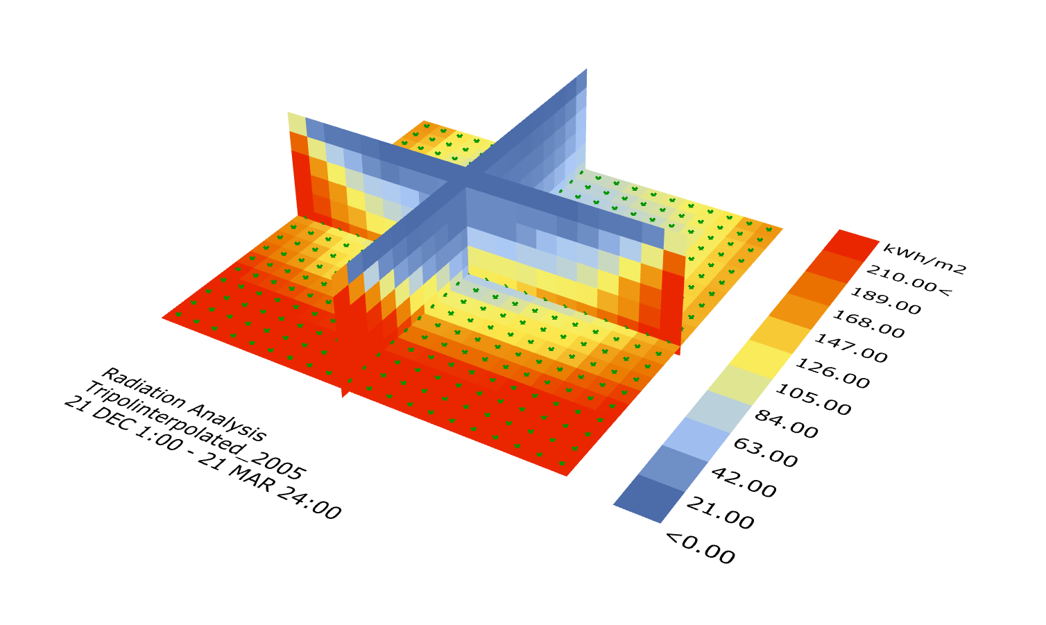
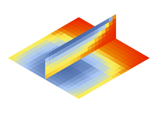
Here’s the results:

Old
image

Revised
image

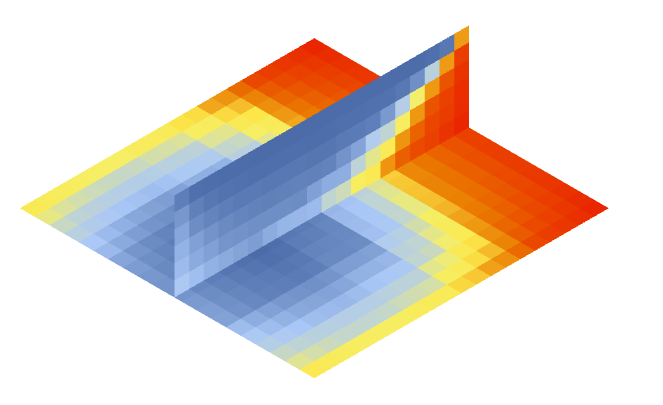
Looks better? Doesn’t match up as perfectly as I thought it would, not sure why, maybe there’s some subtle error in the calculation somewhere I’m not thinking of. At least it’s fast.

At any rate you can test this process out in the attached gh script: Solar_Radiation_Section_SVedit.gh (541.8 KB)

This will be really hard to do with Ladybug since Ladybug generates the vectors based on face normal. You can hack that and overwrite all the vector directions inside the code but that may not be the best solution. It should also be pretty fast to run the same study with Honeybee if you set the number of bounces to 0.

ladybug_ladybug component and you can access them like this:

1 Like

Thanks @mostapha, that’s useful.

So what I ended up doing in the above solution is just adding this line in ladybug_ladybug:

Which was nice since it also gave me surface intersection information along with the patch vector.

S

Update 4:

I realized why the colors weren’t matching as perfectly as I expected. I forgot to consistently set my legend parameter bounds while doing different simulation runs. Rookie mistake!

Fixing that, this method definitely works:

image

@RafaelA, if you’re interested in using this, gh file is here: Solar_Radiation_Section_SVedit2.gh (548.6 KB)

I changed the code to implement Mostapha’s recommendation for getting the patch vectors, which means all changes are now localized into just the modified real time radiation results component.

Also, one more thought on how to appropriately represent this study: the underlying conceptual logic of this exercise is slightly flawed if the intention is to quantify/view radiation at every point along a virtual section (as opposed to an actual physical wall). B/c in reality, the solar radiation at every point along the vertical virtual plane is the sum of all the radiation vectors on that point, not it’s projection on a plane. So to accurately present solar radiation along a virtual plane, it’s more accurate to quantify/represent it with a view factor calculation (i.e how the spatial MRT calcs are done in LB).

S

1 Like

Hi @SaeranVasanthakumar,

Sorry for the delay in coming back to you, only now I´ve found the time to put my mind back to this.

Thanks for the precisions, now I´m understanding the concept behind this calculation a bit better. I had a feeling this procedure was not the most accurate way to get the solar radiation on a virtual plane, but didn´t really know why. I suppose then that for each point in the plane we´d need the view factor calculation to each Sky patch, multiplied by the cumulative radiation of the patch. Is that what you are referring to?

However, as this process gets increasingly complex I´m thinking that @mostapha suggestion could be the best way forward. I´m not sure how it would come out in terms of speed, but View factor calculations take a bit of time and I´m guessing that Radiance is better optimised for that.
@SaeranVasanthakumar Do you still think it is worth exploring the alternative with LB using the view factors?

I´ve tried to use the script you´ve put together (thanks!), however the results for one of the sections (aligned with x-axis) doesn´t match the plan. Do you have any idea on why one section works (aligned with y-axis) but not the other?

@RafaelA,

Yes, I realize why it’s not matching up, I made a mistake in my starting assumption:

The problem is that the starting radiation on the surface discounts radiation from sky patches outside it’s “view”. So the viewfactor of the plane is a constraining factor for the method I suggested, unfortunately.

I agree you should use Mostapha’s suggested workflow, and as you say it’ll be faster if you do decided to explore modeling radiation view factors.

S

1 Like