I have a question about a doubt inherent the new options for the representation of the sunshine exposure with a stereographic diagram in according with the EN 17037.
Precisely for the realization of this diagram with the Ladbug Tools.
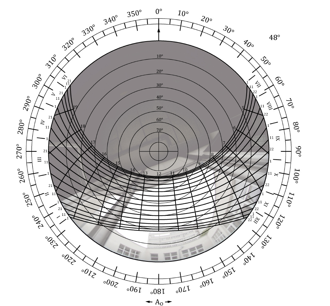
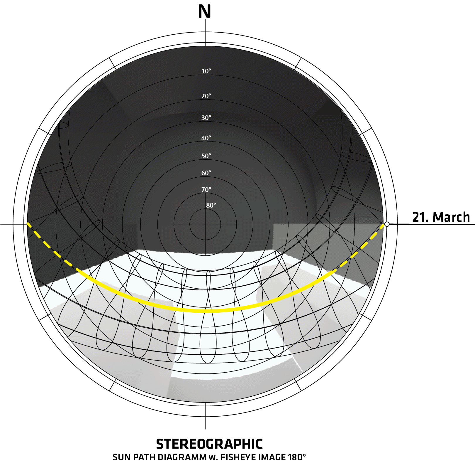
The standard says in the paragraph D.5:
“Wide angle images (Fish-Eye 180°) taken from the point P looking upwards (zenith), with the orientation to the north at the top of the image. The shielding buildings are covered with a stereographic diagram of the sun path.”
I want to replicate the standard using the ladybug tools:
This is my little example:
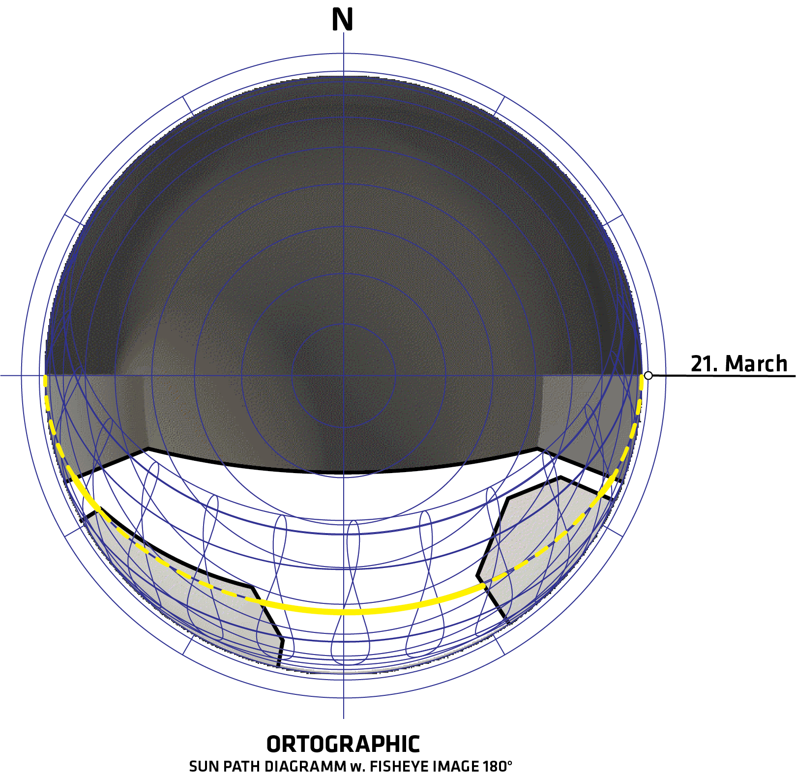
Based on my analysis on March 21, from the point P, the path of the sun is blocked by the 2 buildings, exactly as seen in the example with the orthogonal diagram, but using the stereographic diagram (the one that should be officially used) the result is no longer congruent with reality!!
I think I know how to remedy the issue but I can’t articulate well without ‘doing the thing’; currently working on creating the .gh file, the EPW file URL would assist in a more accurate representation; otherwise I’ll just use Kaunas.
hope to have a solution for you shortly
I think it may be due to the perspective of the image and or the scale of the image being used, for reference I set the document settings to meters, grid to minor=1m major=100m the diameter of the 2D sun path is 4 Major squares so 400 meters.
I obviously have no idea how you generated the geometry of the buildings but if I am not mistaken (I have no professional training or education) If the geometry wasn’t created in a way that would coincide with the perspective created using the prescribed methods of EN 17037 that you referenced then that could account for the discrepancy, the following details on the processing of an image for Hemispheric photography lead me to believe that the issue may be in sizing and translating the coincidence of the edges to scale with Ladybug. also the following .gh has the sunpath tool set up to give you the straight curves of the stereo rathern than the figure8s.
If you use a number slider from a decimal value to a larger than 1 value it may assist in determining what scale of stereo-graph to image scale ratio will proved the correct relationship of hemispheric coordinates from the image to the overlay.
Photographs are digitized and saved in standard image formats. For film cameras this step requires a negative or slide scanner or a video digitizer. For digital cameras this step occurs as photographs are acquired.
Photograph registration involves aligning the photographs with the hemispherical coordinate system used for analysis, in terms of translation (centering), size (coincidence of photograph edges and horizon in coordinate system), and rotation (azimuthal alignment with respect to compass directions).
too kind of you Trevor, thank you very much for all the time you have dedicated to. Tomorrow morning I will take some time to study your advice and be able to discuss it with you …
Greetings
L. R.
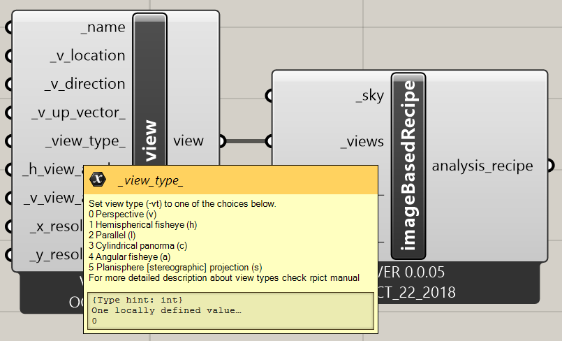
The default hemispherical fisheye view of the HB component, is not the right way for this “job”.
Unfortunately I have no idea how and where edit, the rpict line manually.
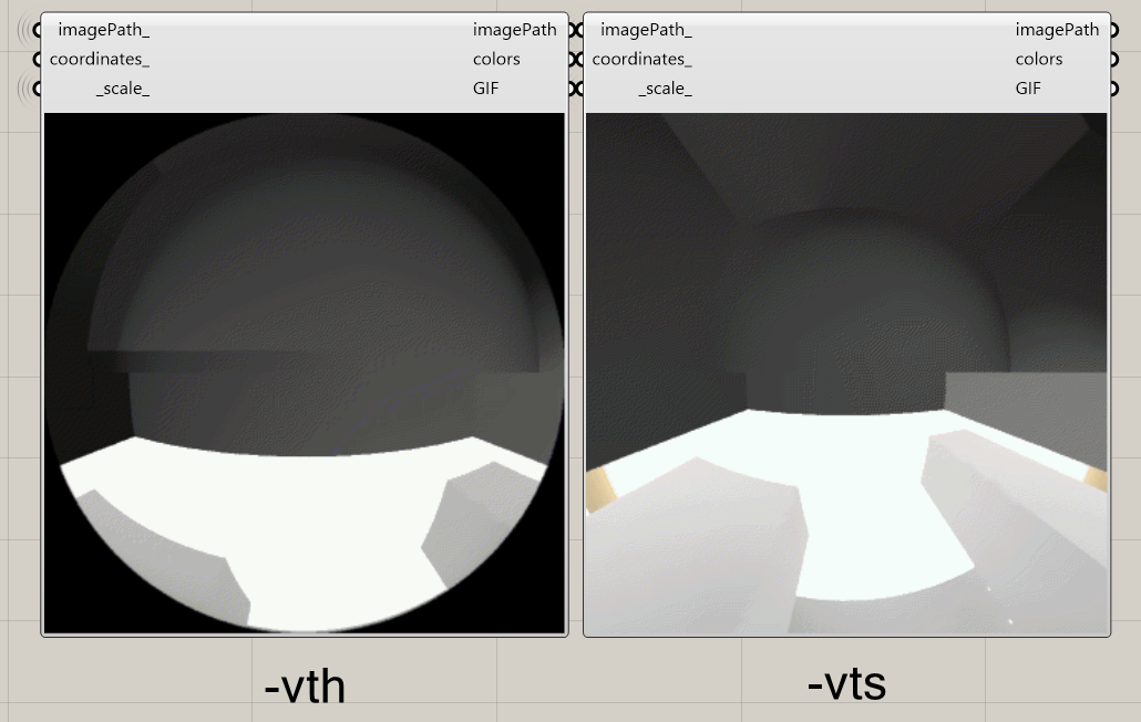
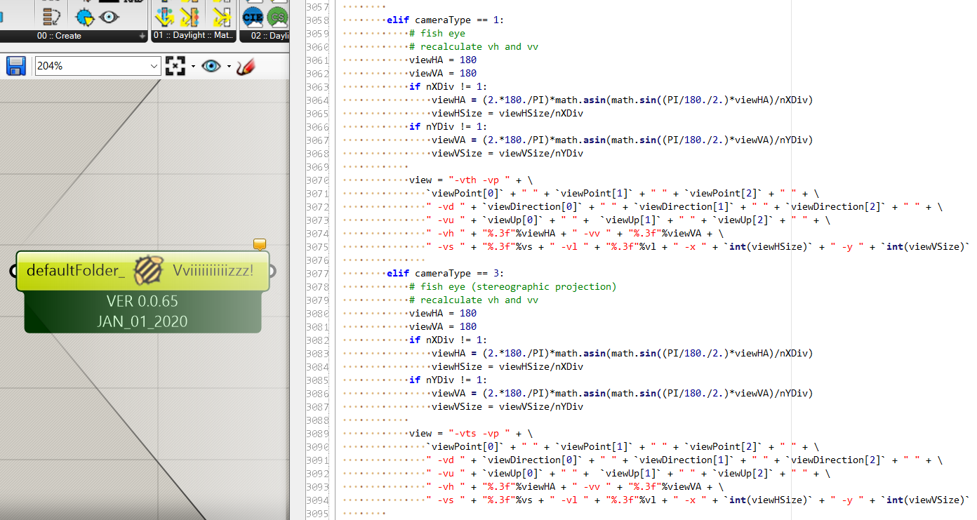
If so, you can run your current simulation setup and manually edit the batch-files in your project folder and execute them outside Grasshopper. However, doing this everytime is bothersome and it does not require much to integrate it as an option for your setup. In the main Honeybee component I included another camera type as seen in the lines 3077-3094 in the image below - the only difference is on line 3089. This is all it takes to create the above image with the view type -vts.
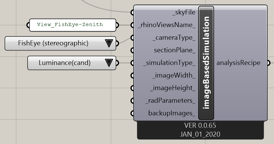
I believe it would be possible to move over to HB[+] as well since it allows one to choose -vts, see image below. However, then I don’t think you can get the Rhino view as easily as the first option (just by typing its name) since you first need to extract the view location, direction and up vector.
Now sorry for my total python ignorance, as in your above image (with the two adjacent images), I do not understand how from an analysis with the exact same components, on the one hand is generated the -vth and on the other the vts version.
You may have missed that I changed the camera type input for the second simulation as well. That’s the only difference between the two analyses in the file I attached above.