I have questions about the sensor points to control electric light and test points on desk level. After locating the test points, I am trying to define the input parameters in the ‘Lighting control recipe’ with sensor points. However, I would like to know the default for the sensor point (especially how big it is). I could manage to define its location, but not sure about its impact. What does it actually sense? Is it the same size as the test points? Do the sensor points and test points on the desk level get a result of an infinitely small point, or is getting the result over an effective area so the fewer points we have the bigger the effective area? For example, if we have one test point, is it averaging the whole floor and using that? And if we have lots of test points, is it drawing a tiny square around this point using this as the area?
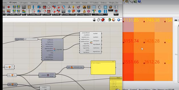
In the image below, I got the colour plot with test points by using the grid-based simulation. But I am not sure if the illuminance values written are the average of that little square, or infinitely small single test point value?
We essentially assume that every sensor used in the Radiance simulation represents the location of an illuminance sensor in the real world, which will be used to dim the lights based on the illuminance at that location in space. So, if you want to model a system with a few illuminance sensors that dim the lights, you just create Sensor Grids with the positions of where those illuminance sensors are in the real space.
And, if you use a whole big grid of sensors in the Radiance simulation, this would be a kind of idealized light dimming system with sensors everywhere dimming a lights that are right above each sensor.
Hi @chris,
Thank you for your reply. I went through the file you sent but got an error of ‘geometry is not a closed volume’. I have tried modelling a box in Rhino canvas, then internalising it with a brep. But, it gave this error. I have also tried to draw surfaces in Rhino and internalise them through ‘HB-createHBsurfaces’ component but got the same error. Do you have an idea how to solve this?
Regards,
Berrak