Fantastic update and I am already using it.
Question @mostapha @chris is it possible to get the U Value or calculation results on a particular point or custom line (say drawn through the assembly) in rhino rather than just along the total path ?
Maybe I just have not discovered it yet.
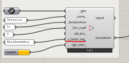
Not sure that I understand the question but you can get U-Values calculated along any “FF Boundary” geometry that you have in your Fairyfly model. So, for example, you can get separate U-Values for frame vs. edge-of-glass vs. center-of-glass in a THERM model of a window sill by just creating each as a separate “FF Boundary” with a separate u_factor_tag_:
Hi @chris I mean can we prob at a specific point or line across the assembly, like so:
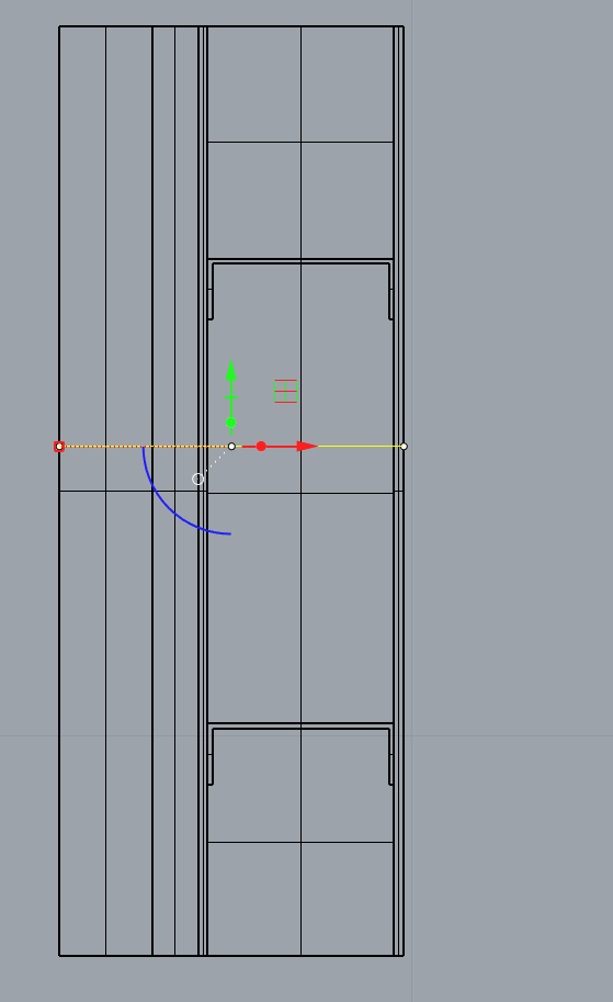
Maybe I am just missing it and it is already possible.
Hi @remyweather ,
I moved your question to a new topic since it’s not directly related to the Fairyfly release.
What you are asking here doesn’t really seem to be about U-Factors, which have the units of W/m2-K. The m2 in the denominator implies that you are looking across two linear dimensions - one of them in the 2D canvas of the THERM model along the outer edge of shape and another coming out of the screen (assuming that the shapes of the THERM model are essentially extruded out of the screen in 2D).
When you remove one of these linear dimensions by saying that you only care about a point along the outer edge of the construction, the units of what you are looking at become W/m-K or conductivity. Not U-Factor in W/m2-K.
If you want to find the overall conductivity along a line, you don’t need any fancy meshing or finite element analysis like what THERM provides. You just need to intersect your line with the shape polygons so that you get the length of the line through each of the polygons. Then multiply each of those line lengths by the conductivity of the material that you assigned to the Shape. Sum up each of those multiplications and you will get the conductance (W/K) along your line. Then divide the result by the total length of your line and you will get the average conductivity (W/m-K) along the line. The math is simple enough that you can set up a Grasshopper script to do this with just native GH components.
Granted, I don’t understand why the conductivity at a point along the edge of a construction is useful, particularly if you have the more complete 2D finite element analysis from THERM. Can you elaborate on why you want this?
Hi @chris thanks for the reply and for moving this.
Understood and you are correct about the m2, units. my apologies.
Reason for wanting to be able to take a measurement somewhere else in the assembly is to potentially have the ability to show that the performance is not the same everywhere in the assembly, this is useful for us
Thanks for clarifying, @remyweather ,
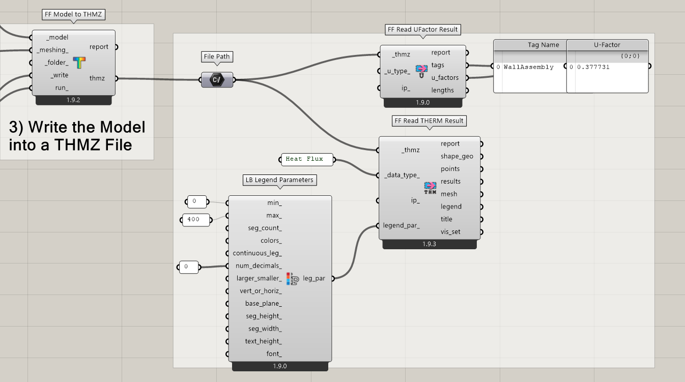
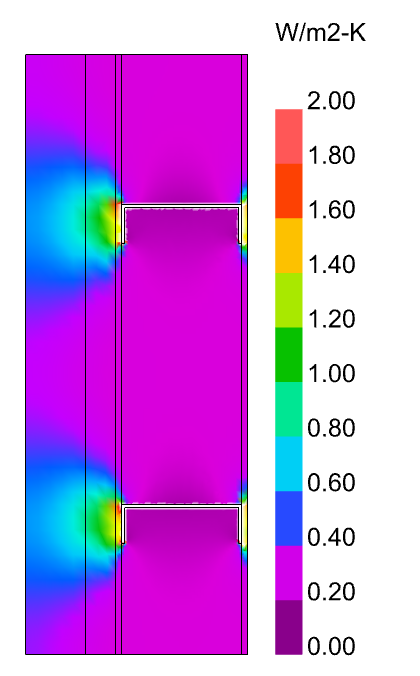
Now that I know what you are trying to communicate, I have a suggestion, which might be a more effective way to explain that “the performance is not the same everywhere” while also giving a more complete view of the “performance” over the whole construction. Instead of trying to give a single number for U-Value at a point along the edge of the model, you can use the “FF Read THERM Result” component to import a colored mesh of the Heat Flux (in W/m2) like so:
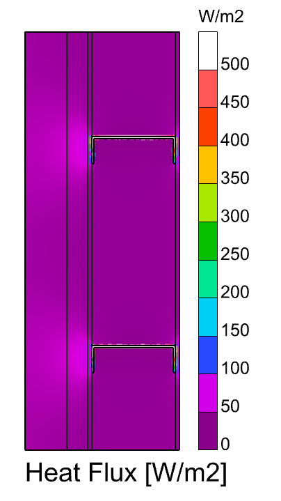
This helps you highlight where in the model you are loosing the most heat (aka. where the U-Value is worst). In the screenshot above, this is clearly mostly through the steel studs. However, you can also appreciate that there is a bit higher heat flow that happens where the steel studs attach to the rest of the construction.
The benefit of visualizing the heat flow like this (as opposed to the method I described in my last post) is that you actually see the heat as a 2D “flow” and not just as a 1D evaluation of conductivity along a line. So, if you are tying to think about how to make the steel stud wall construction above better, you can come up with solutions beyond just “get rid of the conductive steel”. You might, for example, propose a thermal break in the middle of the steel stud. Or you might propose an extra insulated pad where the steel stud attaches to the rest of the construction.
Furthermore, if you really like to explain things in terms of U-Value and you like using the units of U-Value to compare things, you can take the Heat Flux results (W/m2), divide them by the temperature difference of the two boundary conditions across your whole model (in K), and then use the LB Spatial Heatmap component to recolor the result mesh with values of W/m2-K (the same units as U-Value). You can do this like so:
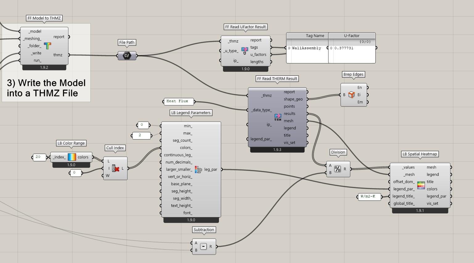
So, even though you are not technically looking at a U-Factor when you do this, it is in the same units as U-Factor, which allows you to make intuitive comparisons to it.
I hope that helps.