Zone Infiltration absolute value-variable results

Hey everyone, thank you for the amazing support you provide to the LB tools community! Since I am still a newbie, I am trying to understand how infiltration and ventilation objects work for anoptimization study I am doing. Specifically, I am using the IdealAir system to simulate a single-zone apartment with a fixed area of 80 sq. meters and while I have assigned absolute values in ach for the zone infiltration, i get variable results when reading the eplusout file. Is this related to the infiltration equation (temperature difference, wind speed) somehow? I would expect to get a constant value and instead I am getting variable numbers (close to the 0,4 ach that I have assigned). Moreover, when opening the idf file of the output at the Design Flow Rate Calculation Method I get Flow/ExteriorArea. What am I missing here? I attach screenshots of my problem and the gh file.Thanks a lot for your feedback.


image

Optimization study_infiltration.gh (842.5 KB)

Hi Lilly,

I haven’t done the digging into this specific issue, but earlier I was looking at e+'s infiltration methods.

At a glance it looks like there’s some variability based on wind speed and temperature (internal and external).

Thank you charlie,
yes I was reading that part as well but in my .idf the coefficients are standard, not depending on the EPW file (see the image below).


I was thinking that it has to do with exfiltration hapenning at the same time with infiltration depending on the density of air between the interior and exterior of the zone.
Also, I think that the flow/ExteriorArea part is because the AbsoluteLoadVals component normalizes the absolute values of the loads and maybe converts the infiltration from ach to Flow/ExteriorArea in the .idf.
If someone can confirm this please!!

Thanks a lot

1 Like

@lillytoul

Re: Infiltration Conversion

Also, I think that the flow/ExteriorArea part is because the AbsoluteLoadVals component normalizes the absolute values of the loads and maybe converts the infiltration from ach to Flow/ExteriorArea in the .idf.

Yes, that’s how I would do it. ACH is just the ratio between the volumes of infiltration air flow per hour and your zones (Flow[m^3/hr]:V_{zones}[m^3]), so you can easily confirm the derived flow per exterior area by multiplying your ACH with your zone volumes and normalizing the result by total exterior area and time:

\frac{Flow [m^3/s]}{ExteriorArea[m^2]} = \frac{ACH}{3600[s]} \cdot \frac{V_{zones}[m^3]}{ExteriorArea[m^2]}

Note: This assumes the ACH is defined for the entire building and one flow rate is calculated for all exterior surfaces.

Re: Infiltration Variance
This is an interesting problem, I agree with you, it does look like the infiltration should be constant based on the settings in the IDF file: all the environmental coefficients are zeroed out, and the schedule looks like it’s always constant (Always On or MYALWAYSON in your screenshots).

I was thinking that it has to do with exfiltration hapenning at the same time with infiltration depending on the density of air between the interior and exterior of the zone.

I don’t think there’s any exfiltration at all when EP uses the DesignFlowRate method to model infiltration. You can see in the IDF editor for the object the input ranges have a minimum of zero, and the temperature difference in the formula below is absolute (and your coefficients are zero for this anyway) - so I don’t see any way for the infiltration flow rate to change directions with the given formula:
image

I think it’s only when the AFN is used, and the envelope pressure difference is calculated that exfiltration is modeled. Are you using the AirflowNetwork (AFN) component in your simulation?

By default, the infiltration air flow rate is constant in Honeybee. Of course, the energy lost/gained from infiltration is going to change with the outdoor temperature even though the flow rate is constant. Are you sure that you’re looking at infiltration flow rates and not the energy gained/lost by infiltration?

Those temperature and wind coefficients that @charlie.brooker pointed out in the IDF schema will vary the flow rate depending on indoor+ outdoor conditions and these properties are exposed in the Ladybug Tools SDK but not on the Grasshopper components. So my guess is that it’s not them but you can make use of them if you find them important. The AFN will also dynamically compute infiltration rates as @SaeranVasanthakumar points out. But you will only have this if you’re using the “HB Airflow Network” component.

@chris

I haven’t checked the model, or looked at the relevant EP docs in detail, but the various screenshots of the model she’s shared are consistent with the discrepency she is pointing out: the zone infiltration rate output varies throughout the simulation, even though all specified inputs should produce a constant, unvarying flow rate.

Are you sure that you’re looking at infiltration flow rates and not the energy gained/lost by I filtration?

Looks like it. This graph she shared earlier is titled as the zone ACH rate, and the actual values reflect the expected flow rate magnitude, (with exception that it’s not a constant):

Those temperature and wind coefficients that @charlie.brooker pointed out in the IDF schema will vary the flow rate depending on indoor+ outdoor conditions and these properties are exposed in the Ladybug Tools SDK but not on the Grasshopper components. So my guess is that it’s not them but you can make use of them if you find them important.

From the screenshot she shared of her IDF, those temperature/wind coefficients are already set to zero in her model, so they can’t be contributing to that varying flow rate. Admittently, there’s some ambiguity in the screenshot about the value of the Velocity Squared Term Coefficient for wind which looks like its not set explicitly, but the default is zero, so it shouldn’t be the cause of the variation:

You can also see there that the infiltration schedule is also a constant Always On, so that also can’t be a cause of the variability.

The AFN will also dynamically compute infiltration rates as @SaeranVasanthakumar points out. It you will only have this if you’re using the “HB Airflow Network” component.

Yeah, I was wondering if a possible explaination here might be the accidental use of the AFN, triggering a completely different infiltration calculation. At any rate, I can confirm this isn’t the case, I checked her script and its not in there.

So, if we go by the Design Flow Rate calculation used by EP (from the screenshot above it’s Infiltration=Idesign * FSchedule * (A + B*|(Tzone-Todb)| + C*WindSpd + D*WindSpd**2)), that output Infiltration should work out to a constant 0.4. I’m pretty curious, where the source of this variance coming from…

2 Likes

@lillytoul

I figured out the cause of the variation, or at least the main contribution. EnergyPlus is using an outdoor air density calculation when converting the infiltration into a mass flow rate which is derived from site air pressure and temperature. So the fluctuation reflects changes in the site outdoor temperture and air pressure. There doesn’t seem to be any mention of this at all in the EP documentation, but this Unmet Hours post[1] breaks down the formula they’re using - essentially adjusting pressure for zone height, then converting this to a density with the ideal gas law.

All the reported EP infiltration volume-based outputs takes this mass flow (derived with an outdoor temperate-adjusted density) and converts it to a volume with an air density derived from the zone temperature (otherwise the same formula). Thus all volume outputs (including the ACH) will differ from their input value.

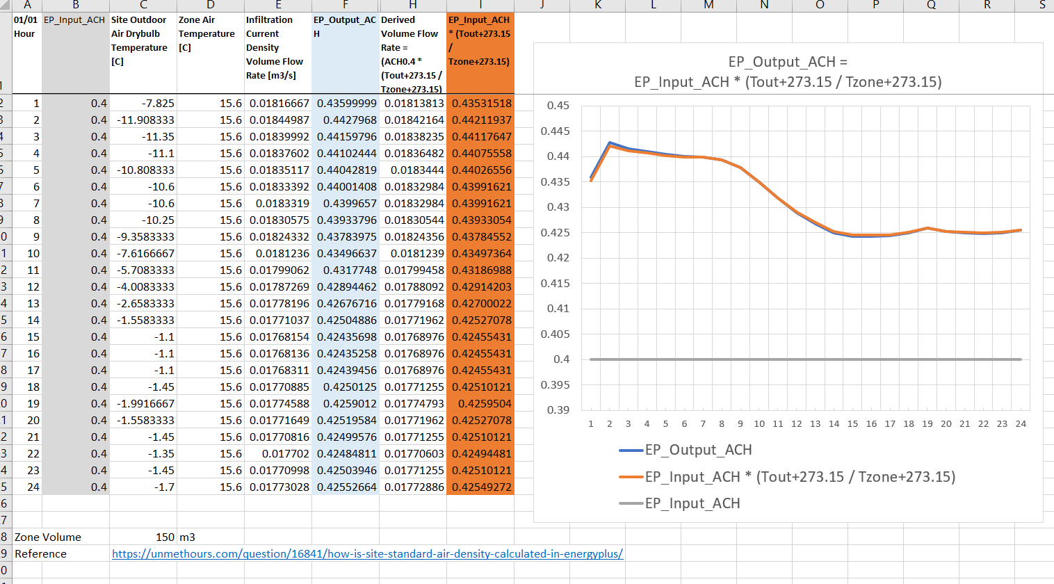
if you just want to convert between volume flow inputs and outputs, all of this simplfies to a simple ratio between the outdoor and indoor temperature which can be multiplied to your inputs to match the EP output. I.e:

ACH_{out} = ACH_{in} \cdot \frac{T_{out} + 273.15}{T_{in} +273.15}

Here’s an example from a simple shoebox model I tested this with:

Although, its best to avoid using the volume-based outputs altogether if there’s a choice. The mass-based outputs are what’s actually being used in EP’s heat and mass balance, and thus are reliably downstream of any adjustments EP makes that may or may not make it to the documentation.

[1] Note that the formula in that post refers to the “Standard” density, which is a single constant density from a single assumed value for the pressure and temperature. Substitute the actual pressure/temperature values derived/interpolated per timestep by EP (as illustrated in that Excel sheet) to get the actual, varying densities.

4 Likes

@SaeranVasanthakumar @chris
Thank you so much for your time and effort to solve this mystery! I think what you found explains the variation and I will try to avoid using volume-based outputs, as you suggested.

Cheers!

Excellent detective work, @SaeranVasanthakumar !
Thanks for getting to the bottom of it and letting us know. Everything makes sense.