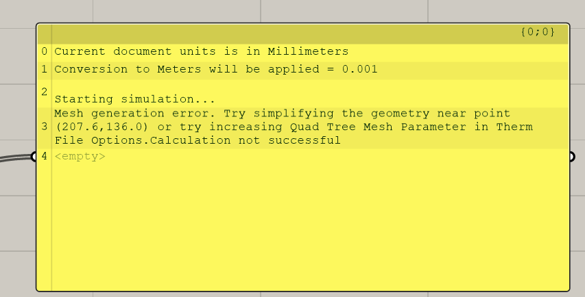
I’ve only been dealing with Therm and Honeybee for more than a week and would just like to write down some experiences before my question. I hope it helps people:
Even the installation of all the required plugins is not entirely intuitive. But if you do a bit of research in the forum and use the right versions, it should be doable. For me it now works well with: ladybug 0.0.67; honeybee 0.0.64; Therm 7.6.1.0; Rhino 6.35. (Attention: The Read-Therm component 0.0.63 does not work).
Furthermore, I could not achieve comparable U-values for a simple wall from a construction with flixo right from the start. However, this was due to the setting of the radiant energy. Here is the reference to the customRadEnv component, where the view setting can be set to 0.
One challenge is the geometry description. There must be no closed cavities. Here I refer to a discussion in the forum. (THERM - Window section issues - #11 by chris) In addition, it is advisable to define all geometries directly as polylines.
In the meantime, I have a definition for which no error message appears when I create the file for Therm. However, the simulation does not yet work. (Error message: The geometry contains voids or overlapping areas. The edges surrounding these areas are highlighted in red. You must fix this problem before simulation. The geometry contains overlapping areas, which in some cases can be corrected by regenerating the boundary conditions. The edges surrounding these areas are highlighted in red. You must correct this problem before simulation. ID(s): xxx The model geometry and boundary conditions must be correctly defined before a calculation can be performed).
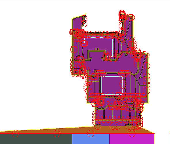
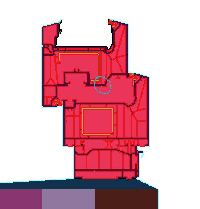
When I open this file in Therm, I am also informed of the gaps. It looks something like this.
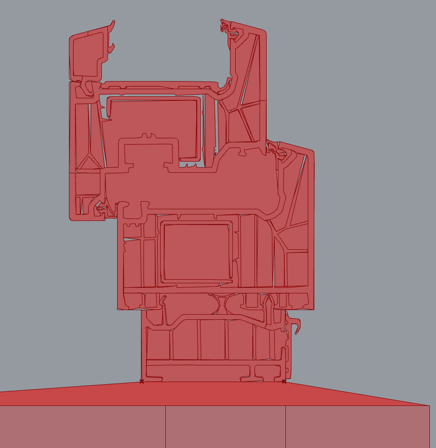
However, I can’t trace the gaps (and I can’t see them visually in Therm). When I created the geometry in Rhino, I converged all curves to polylines at Berginn. Then I created the inner cavities based on the existing polylines and declared them as air. When I intersect the line of the air with the adjacent material, I get a resulting intersection line (so it is really on top of each other) Also when I bake the result of the ProbRegion, I get a continuous surface. And the resulting boundaries also result in only one boundary.
Now I was at a bit of a loss as to what else I could define.
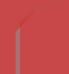
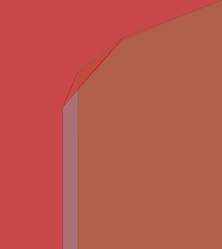
I rewrote the definition from millimeters to meters. However, the material definition is then quite unprecise:
But this leads me to the assumption that Therm (or the Honeybee component) rebuilds the lines (even if they are already polylines). But then it is logical that gaps are created when lines that are already adjacent to each other are rebuilt independently of each other.
Now the question: Can I still change tolerances somewhere? Should it not matter whether the definition is in millimeters or meters? Is my geometry too complex for Therm? Can I define that lines are not rebuilt? How can I make progress here?
