Hi friends,
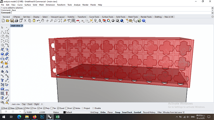
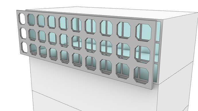
I wanna compare two skins with different pattern to analyze which one is more efficient in terms of energy usage. But the output of these skins is exactly the same. Literally I don’t know what’s the problem.
analysis model 1 (LBT).gh (127.0 KB)
analysis model 2.gh (134.8 KB)
Some general advice for interpreting models: If you’re getting extremely similar results from two different inputs, and you think this may be due to an error in your setup, you can easily check this by modifying your inputs to two very different conditions. So for example in this case, remove the openings in one skin, and increase the opening in another. If the results are still similar it’s a problem in your workflow, if not, then it’s probably accurate and you’re intuition about input sensitivity was wrong.
Is the difference between both skins just the opening geometry of that shading surface? If so, then given how similiar the geometry is, I would expect the resulting energy consumption to be extremely similar.
Hello thogether
@SaeranVasanthakumar I like your discreet way of keeping focus. Very good suggestion.
@SimaKhayami94 you may also have a look here.
sort of off topic?
https://discourse.ladybug.tools/t/2018-in-a-nutshell-and-the-plans-for-2019/4946
also this one maybe something to consider
https://ladybug-tools-academy.teachable.com/
I support @SaeranVasanthakumar advice.
I myself tried somethings in your model and the results were identical indeed. My trials went through to cancel all the program, constructions, HVAC and other settings. Just keep the geometry, so there is no room for errors in the setup. Just using default values.
My conclusion of this is the shading elements, even though look different they are pretty much the same (in their proportions, openings, etc) so they don’t influence differently the Room to give different results.
You know, @SaeranVasanthakumar, how E+ relates to the resolution of the shade elements? My intuition is that in this case the calculations can’t note the difference in the geometries.
As a note for the model, you don’t need the extrude for the shade element. It does not affect the result but duplicates the calculation time (literally twice the time).
-A.
Yeah this for me: learning that, when any simulation model is properly rigged:
getting unexpected / undesired outcome of a simulation:
learning to trust the science, trust the validity of my work in terms of:
These are my results and they are correct.
I’m assuming they touch this topic in relevant Uni majors, though I have no idea as I’ve never been ![]()
That was a huge hill to overcome for me personally, the proper scientific process of building physics simulation and analysis.
Using software and doing the things; that curve seems like the easier one IMO, getting comfortable and confident in terms of designating desired output and ‘correct per the user_input of the simulation model and parameters’
THAT to me has been the hardest part.
Wholly agree in; make a drastic change to one of the two current studies geometry to determine if the simulation is respondent correctly as desired:
that will give you your answer I feel like
Hi dear @SaeranVasanthakumar
As you said I tried this way and even I delete all of the holes but unexpectedly the result was as same as those with holes. I suppose the problem is in workflow but I can not realize what could it be.
Hi dear @AbrahamYezioro
Thank you for your help. I also tried a shading skin with no holes, but the output was as same as those with hole. Don’t you think there is a problem in workflow?
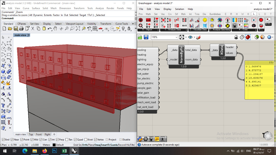
Outputs of this skin also was as same as the two before:
Hi dear @TrevorFedyna
Thank you for your suggestion. I exactly did what you said but unexpectedly outputs was the same again.
Below is the skin I tried and output was as same as the two before:
OK.
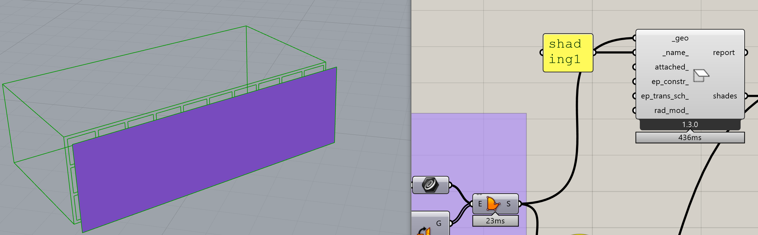
I think i’ve found the reason of the identical results.
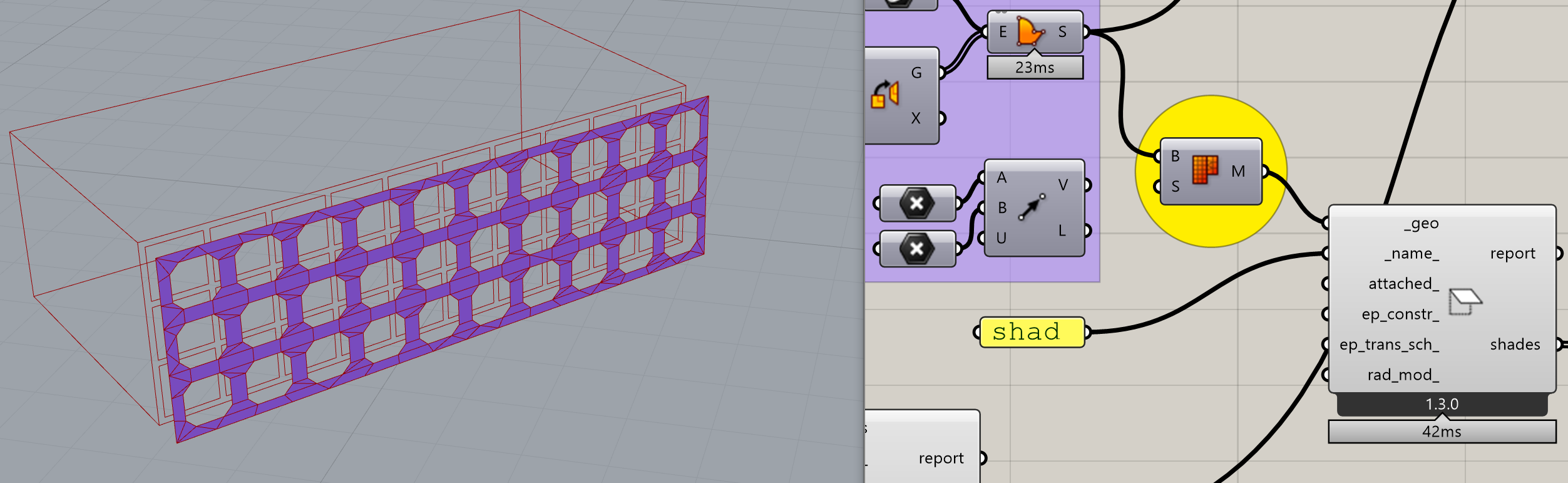
When creating the shades using the Boundary component the output is a trimmed surface. Usually LBT knows how to deal with such surfaces but in this one not so much. When writing the idf the resulting shading surfaces are an untrimmed surface (even thought the VizByType shows them right). Meaning, a complete filled surface, without the holes in it. That’s why, doesn’t matter the size of the holes the resulting surface, IDF wise, is always a filled/untrimmed surface.
@chris, tell me if i’m wrong here. If i’m not, what would be the recommended process to avoid such situations? many users use, from what i see in other topics untrimmed surfaces. I don’t know the reliability of their results now …
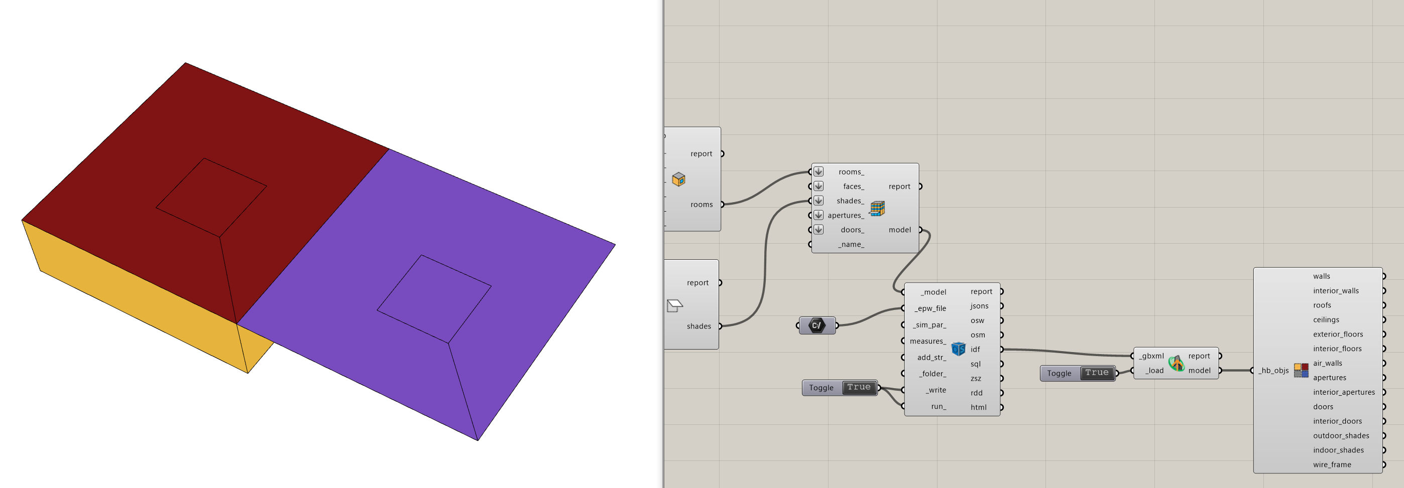
I catch this using the Dump/Load GbXML components and visualizing the shades and also the Legacy ImportIDF.
What i did is passing the trimmed surface through the MeshBrep GH component to create a mesh (instead of the trimmed surface). I believe that now LBT has better and robust functions to do that internally, but not sure if this is true.
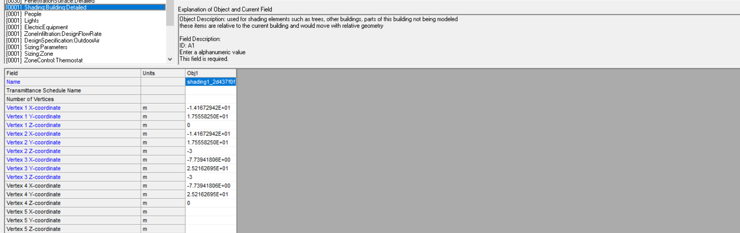
This is the result of using the trimmed surface
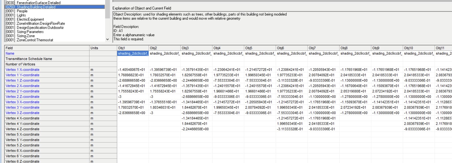
And this is the result of using a mesh:
Attached the, simplified to the minimum, files. The results are not identical now … but very similar (i believe, for the reason i mentioned in my previous post).
-A.
analysis model 1 (LBT)_AY.gh (558.9 KB)
analysis model 2_AY.gh (567.2 KB)
Ah thank you to the moon and back dear @AbrahamYezioro .  That was a great help for me. I think this would work.
Nice detective work @AbrahamYezioro! That is a very subtle bug.
You know, @SaeranVasanthakumar, how E+ relates to the resolution of the shade elements? My intuition is that in this case the calculations can’t note the difference in the geometries.
Yes, it’s an interesting question. The shading calculations are not something I understand completely myself, since there’s like 5 different algorithms for shading, and I haven’t even tried the more accurate ones. The reason I think minor changes in geometry won’t drastically change the EUI is that reductions in solar radiation from shading tend to be small relative to the other loss/gain components. In particular, the conduction loss/gain driven by air temperature tends to be larger: glass conduction is highly correlated to solar radiation (higher U-values increase solar radiation transfer), but it’s energy impact is felt all the time, rather then the few hours shading has an impact.
But I say typically, because there are exceptions. A shallow zone with a large curtainwall like this design actually seems like a good baseline condition for this type of study. Moving away from annual metrics that wash away extremes values, and looking at peak load conditions is the other obvious example of where solar radiaiton can play a huge role in energy consumption.
Using software and doing the things; that curve seems like the easier one IMO, getting comfortable and confident in terms of designating desired output and ‘correct per the user_input of the simulation model and parameters’
There definitely could be more resources to help with this. However, I think this also speaks to a major flaw in the way the AEC industry approaches simulation. The conventional way of relying on a single physics-based simulation as the source of truth for the building puts too much emphasis on a single value, and it’s derivation by perfectly following various standards/conventions.
We should be building hybrid models that combine physics and probabalistic models (derived from empirical datasets and the propogation of modelling error attached to various simulation workflows). It’s faster, more robust and more accurate, but more importantly, provides a lot more information/context about your building.
Good point again @SaeranVasanthakumar that’s where I’m headed to.
My background is an information I received some years ago by one of the top crash analysts in the automotive industry. He told me even they have to “tweak” the logic a bit to receive proper results.
Still trying to find out what this is in case of BEM with Ladybug tools.
And of course there is also the part of reliability of the software.
Well shown here in this case by @SimaKhayami94 's insistence and @AbrahamYezioro 's detective work.
I think the background why Salome Meca was made an open source project applies here too.
OK we don’t build atomic power plants here, but the basic idea of creating a bug free software publicly is a good argument speaking also for Ladybug and cloud be pointed out more.
I think it’s possible that you are just experiencing a visualization issue, @AbrahamYezioro and the simulation results are fine. Does the IDF file only contain 4 vertices for the shade? If not, then Honeybee is just feeding the list of vertices to EnergyPlus as a single list that winds inward to cut out the holes, which is a valid way to pass vertices to Radiance and I’m pretty sure is also a valid way to pass them to EnergyPlus (at a minimum, it should be fine for the PixelCounting solar distribution). However, Rhino doesn’t display lists of vertices like this correctly. Are the solar gain results very different between the meshed case and the trimmed surface?
More infirmation can be found here:
I was wrong about it being a visualization issue (the holes are not being passed to EnergyPlus in the “Model To OSM” component). However, I am correct that passing the geometry as a single list of inward-winding vertices is a valid way to pass the geometry to EnergyPlus. The bug is just that I’m forgetting to do this in the “Model To OSM” translation.
All of the Direct-To-IDF methods (used by annual and peak load components) are not affected by this bug and I’ll aim to push a fix for the “Model to OSM” later today.
Great @chris,
I was about to post an answer to your comment about the visualization, but i see now that it is not necessary. In short, it is not, and i’m happy you get the source now.
Just for the sake of how the IDF was registered, this is the TrimSurface option:
And this is the Mesh option:
Thanks!!
-A.
Thanks again, everyone, for reporting and verifying this.
I just pushed a fix into the development version of the plugin:
You should be able to get it with the LB Versioner in an hour.
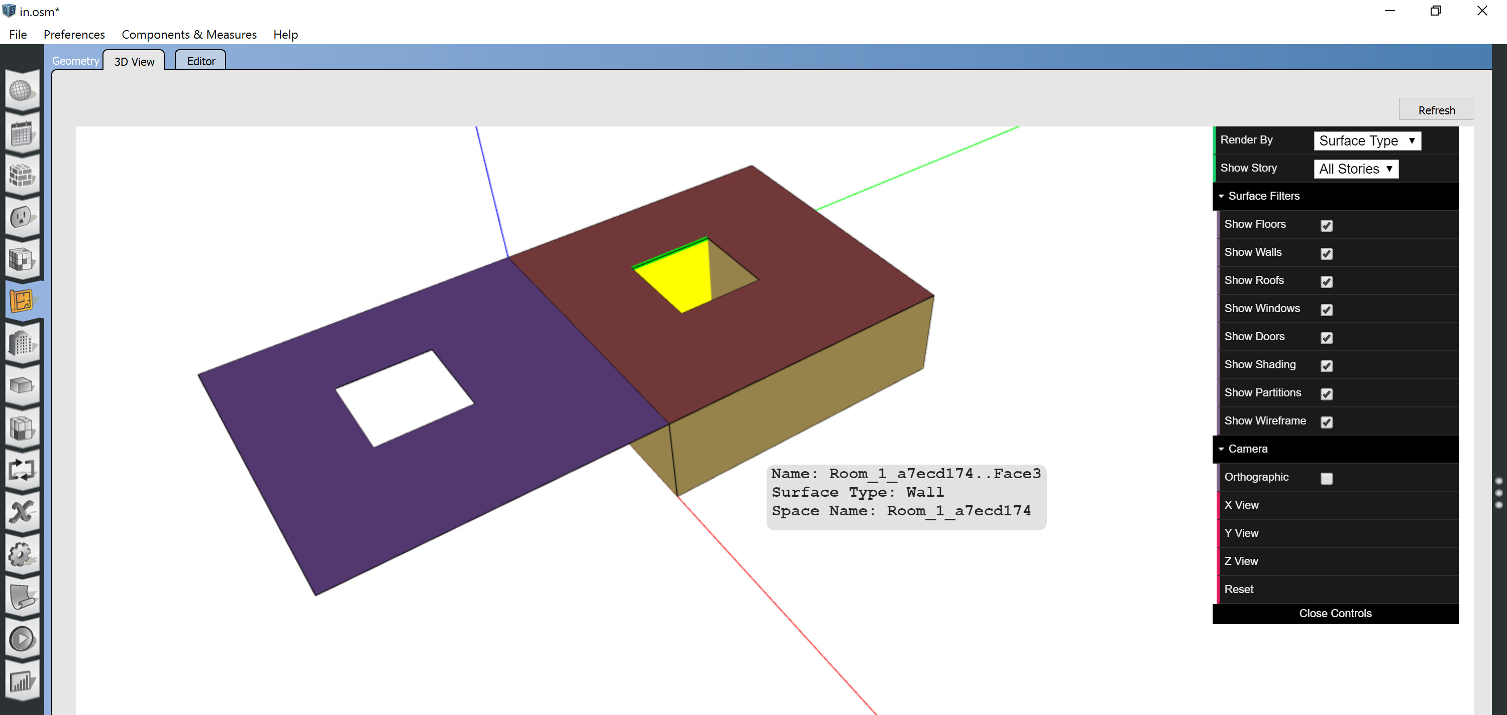
I verified that Rhino will have some issues displaying the geometry when you import it back from IDF:
However, the geometry is correct for EnergyPlus simulation and you’ll see the geometry display correctly in the OpenStudio App:
Thanks @chris!!
It is working … of course.
There is a slight problem checking the IDF file. The IDF editor can’t open the file. Probably the ShadingDetailed object is too long. I had something like this in the past. I’ll check how to solve and report back here.
Thanks again,
-A.
Thanks, @AbrahamYezioro. Your diagnosis of the IDF Editor issue sounds likely (I have had a few cases of my own where I’ve maxed out the number of lines that can be displayed).
FYI, I was able to figure out a way to get Honeybee’s mesh-based visualizations to display the holes correctly when you import the geometry back from IDF/OSM:
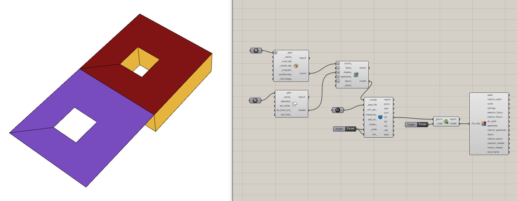
The Brep-based visualizations that you get from the “Visualize All” and “Visualize Quick” components will still struggle to display the holes correctly when you import the geometry back from IDF. But you should now be able to trust the mesh-based and wireframe visualizations going forward.