Fairyfly user feedback

Hello everyone, first off a huge and hearfelt THANK YOU :smiling_face_with_tear: to everyone who contributed to making Fairyfly! I’m very excited about the new tool, which is why I tried it out as soon as possible. I’d like to offer some feedback from my first experience.

Feedback #1
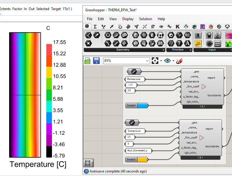
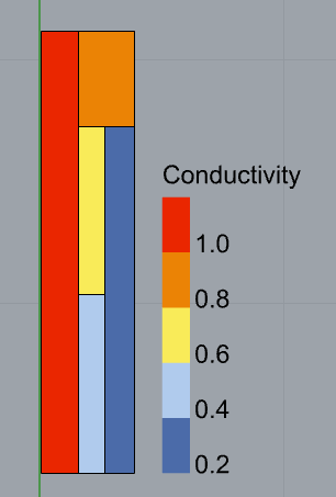
So far I have tried making a grasshopper definition from scratch using some random geometries and random material specifications. However I had an issue with how the boundaries were being defined, in this case I used a single line on the left side (no issues here), and a single line on the right side. In a couple of lines you will see why this is problematic. Here’s the shape geometries:
image

I kept struggling with the THERM simulation and getting this error:

You need to have at least two non-adiabatic boundary conditions to do a simulation. Check your boundary condition definitions.Calculation not successful

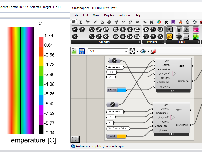
Well, I figured that the right side boundary maybe had to be broken down into 2 pieces because I had 2 material shapes on that side. I found there are two ways to fix this, either

  • using 2 separate boundary lines, each coincident with the 2 shapes on the right, or
  • using a single polyline with nodes coincident with the shape change.

Maybe this is common knowledge among THERM users, but it had me scratching my head for a good 20 minutes. It would be nice to have Fairyfly do this boundary geometry check automagically and break down the geometry if necessary (kind of like how the HB Intersect Solids did with rooom geometries).

Feedback #2
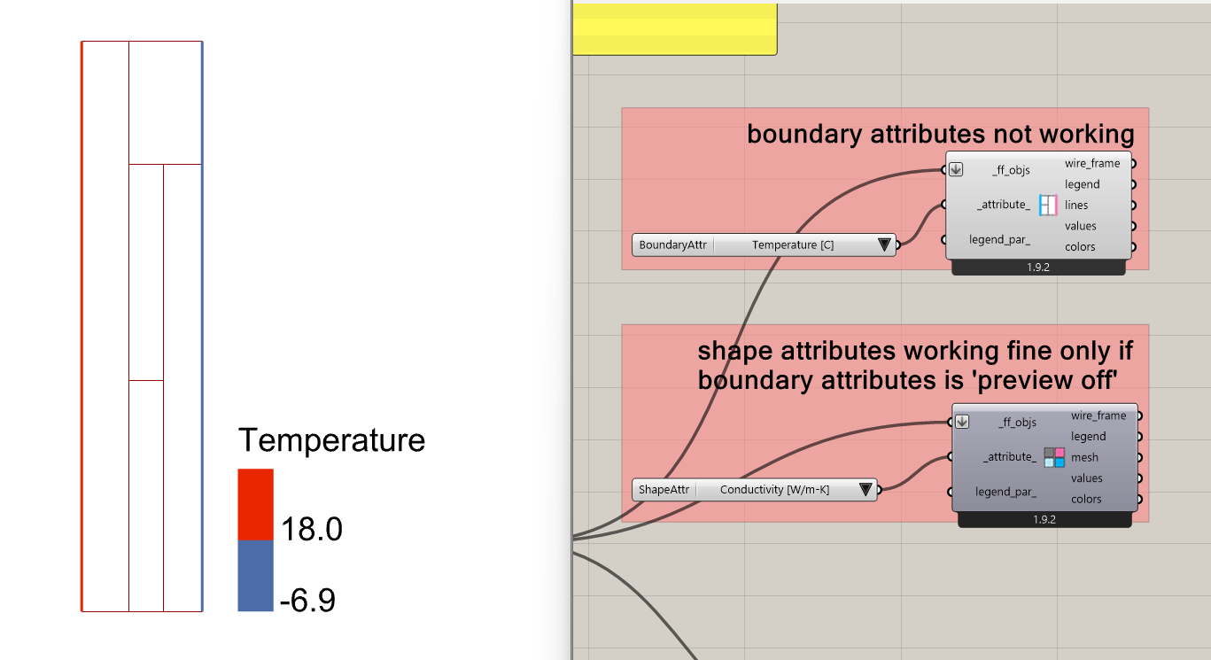
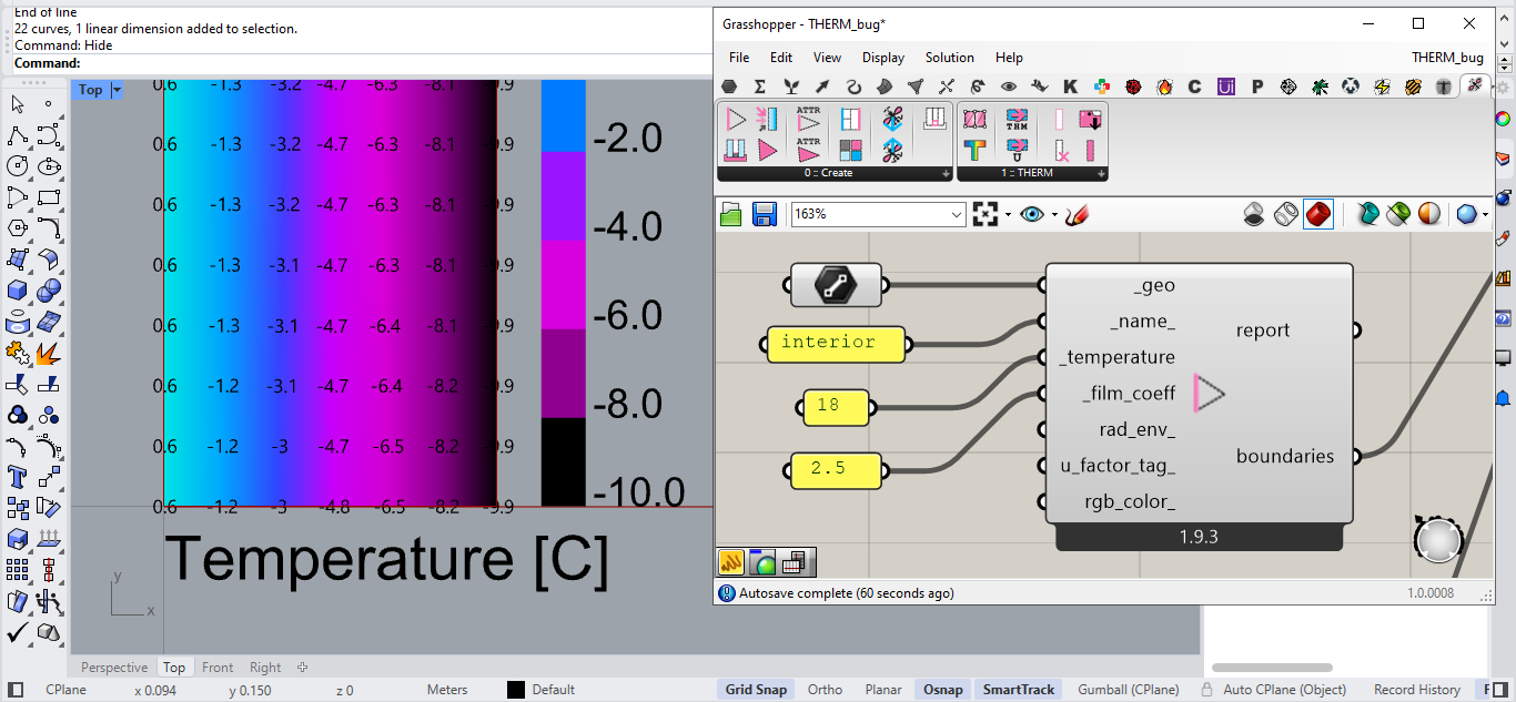
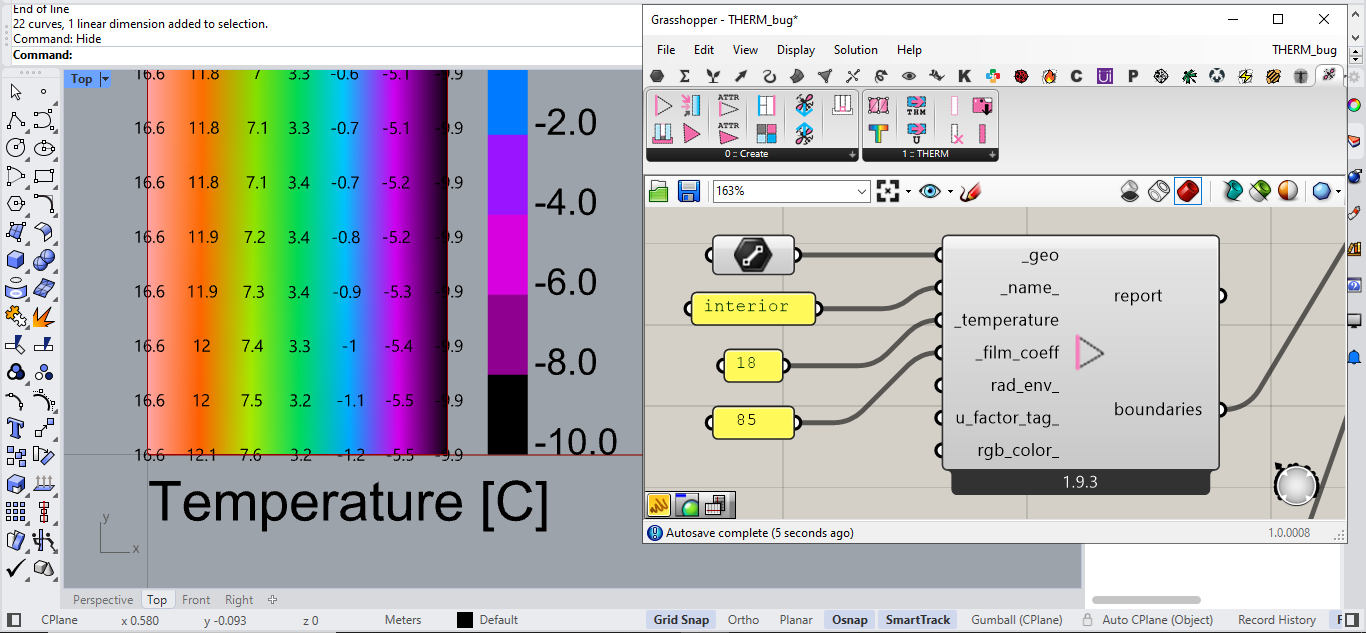
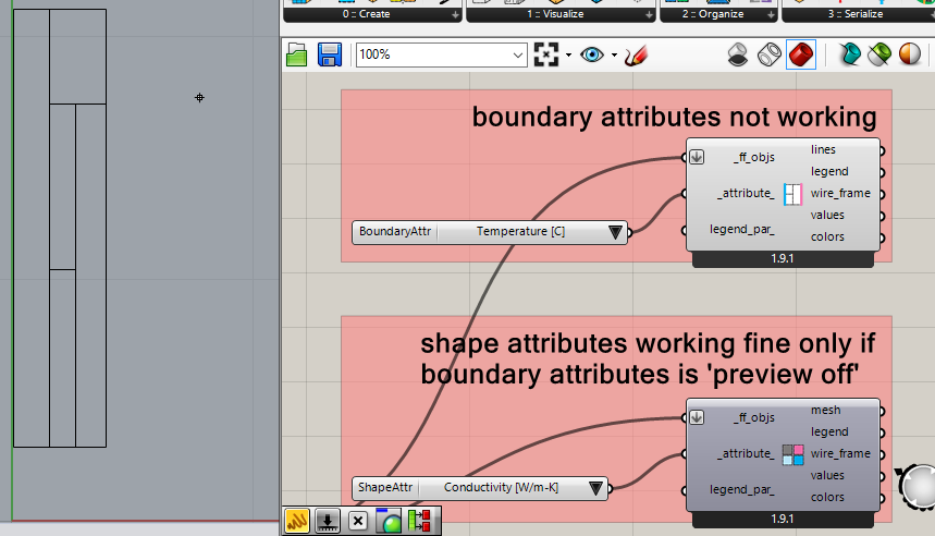
I can’t seem to make FF Color Boundary Attributes work in the Rhino viewport, in fact just having this component preview on, it makes FF Color Shapes Attributes disappear from the Rhino preview. However, it’s working under the hood because I can get the attributes from the component’s outputs.


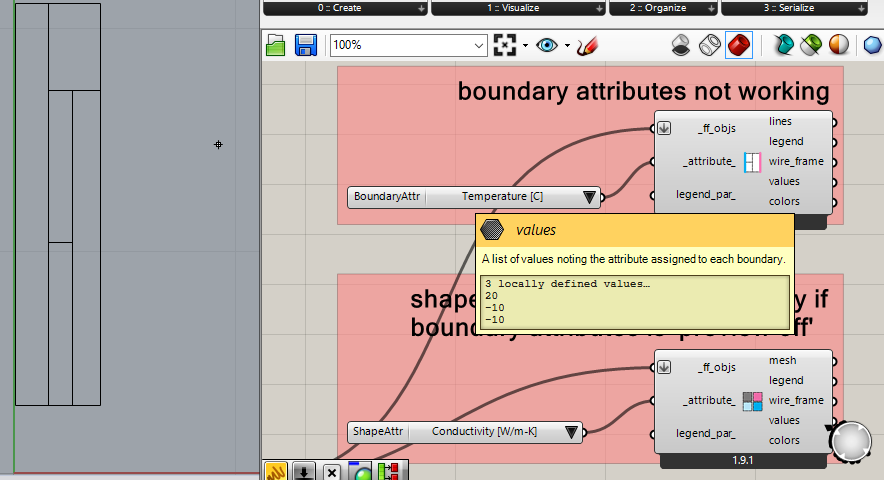
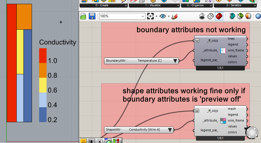
Turning FF Color Shapes Attributes preview off does nothing to fix the problem. I imagine this is a bug.

Feedback #3
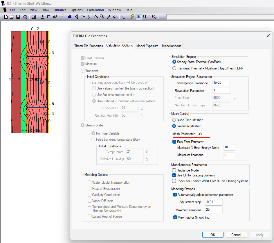
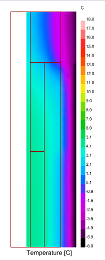
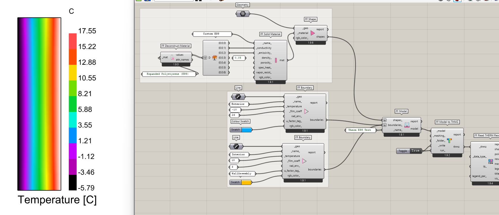
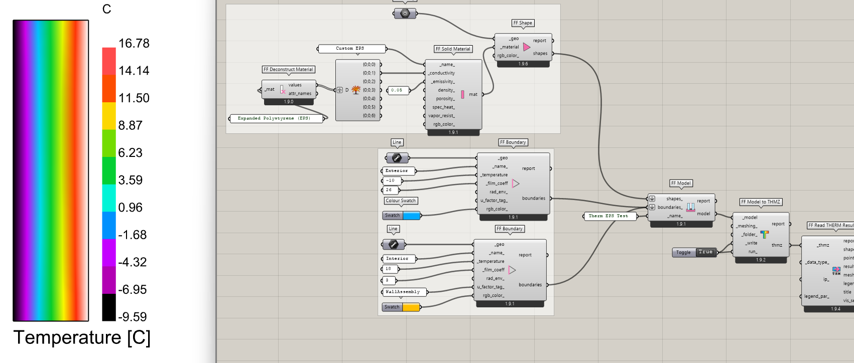
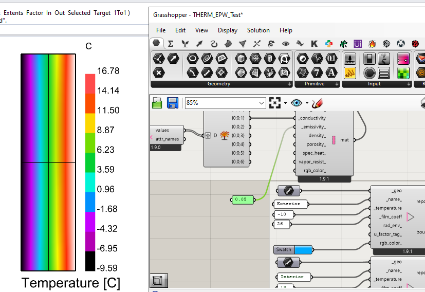
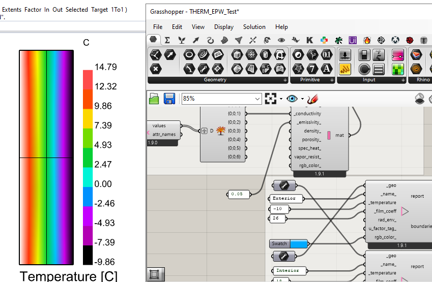
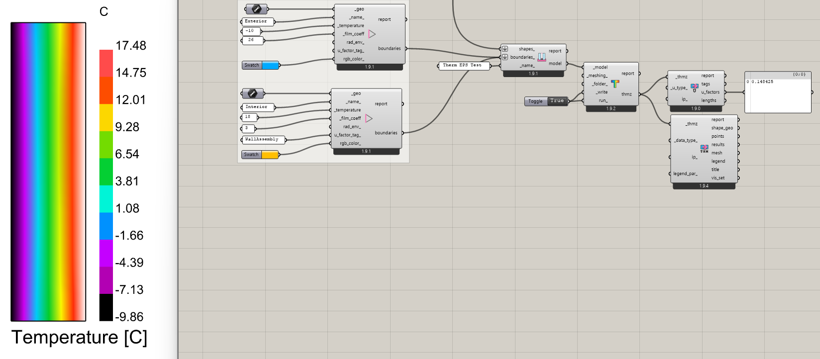
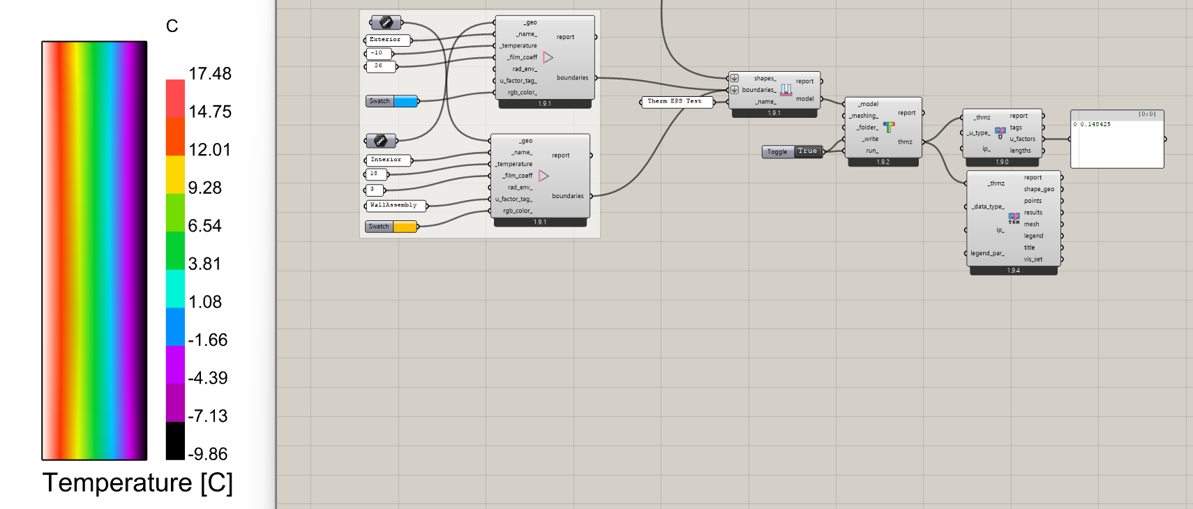
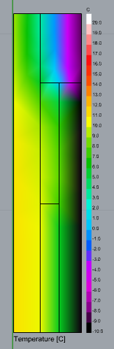
After finally getting things working and seeing the simulation results I started playing around with the legend parameters to see if I could get the whole rainbow from the thermal palette through my materials, but it seems like the mesh is a little coarse and the gradients jump from one color to another, while skipping the intermediate colors (see the bottom side where it jumps from black to green without going through purple-blues). This makes it harder to visualize what is happening throughout the materials. Is there any way to further refine the mesh before running the simulation?
image

Thanks in advance, I will be looking forward to further FF versions.

1 Like

Hi @Gspahr ,

Thank you for testing and for the feedback.

  1. You are right that I was so concerned about the inverse of this case (the Boundary line is shorter than that of any Shape segment) that I didn’t really consider the inverse (the Shape segment is shorter than the boundary line). I just added a check for this in the THMZ translation process, which will split the boundary line for you with the shape vertices:

With this tweak, you should have no problem running the models in your screenshots where there is a single boundary line segment that adjoins multiple shapes.

  1. Thanks for letting me know about this. I actually did most of my testing in Rhino 7 in order to have sample files that any of our users could run (even those using old versions of Rhino). I did not realize that the way the FF Color Boundary Attributes component interacted with the Rhino 8 DisplayPipeline was not working. Admittedly, there is still a lot to the Rhino DisplayPipeline that I do not fully understand but I made a change to the component here, which I have verified works in both Rhino 7 and Rhino 8:
  1. Lol. This is definitely the type of comment that I prefer to get. It’s like you are telling me the new THERM mesher is too good! I am pretty sure that I can give you the smoother mesh you want by just exposing the meshing parameter for the new Symmetrix mesher. Give me until tomorrow to get this into the Grasshopper component but, if you want to see what I am going to do, you can open your Grasshopper-exported THMZ file in the THERM interface and go to File > Properties > Calculation Options. Then up the Mesh Parameter to something high like what I have done here:

Then, simulate your model in the THERM interface, save the THMZ file, and load it back up into Grasshopper. You should see that the mesh is a lot finer and your colors look smoother. If you confirm that this is what you want, I will try to expose the MeshParameter on the FF Model to THMZ component tomorrow.

The two fixes that I pushed should now be available via that LB Versioner component if you want to get the updates on your end and test them. Thanks again for all of the feedback!

2 Likes

Thank you so much! The trick you proposed in the third point indeed does the trick beautifully: after a couple of tries it looks as if 20 is a good number for the Mesh Parameter. It did however shift the mesh to the right of the original geometries, not sure why.

As for the Display Pipeline issue, I managed to get the boundary visualizer working in a different file that I also started from scratch. I still don’t know why it happened in the first place, but I can send you my definition for you to find out. Turning preview on for the boundary visualizer also seems to make the results disappear from the preview.
THERM.gh (65.5 KB)

Hi @Gspahr ,

I exposed the ability to change all of the mesh settings here:

… and you can now get the new “FF Meshing Control” component using the LB Versioner, which lets you customize the mesh parameter and other parts of the meshing operation:

With the change above, I also set the default mesh parameter to 20 so that you typically get a pretty smooth mesh.

I was not able to recreate you issue with the result mesh becoming offset from your original geometry but perhaps you changed more than just the mesh parameter when you opened the THMZ in the THERM interface? Maybe you also changed the origin of the THERM model? If you can recreate the issue again, let me know.

As for the boundary visualization, your THERM.gh file did not have the updated FF Color Boundary Attributes component in it (version 1.9.2). Once I ran the LB Sync Grasshopper File component to update it, everything seems to be fine:

1 Like

Thank you @chris, meshing options are working as intended. May take a little longer to simulate with a very fine setting like 50, but still, it’s very quick (it’s just a few seconds, but the resulting mesh can be a little intense to process).

As for FF Color Boundary Attributes I wasn’t able to recreate the issue either, so I don’t know what happened, perhaps it was the virtual environment on my side. The component is working just fine now.

I will try to recreate the shifting geometry issue for my next post.

1 Like

Hello @chris, just a quick update. I wasn’t able to recreate the shifting geometry issue, still I have no idea why it happened. I will keep an eye out in case it happens again.

I recreated the workflow from my first try with new random shapes and this time everything went smoothly. Down below is a comparison from THERM and from FF.


LBT screenshot

While playing around with visualization setttings I came across a new pet peeve with how isotherms are drawn inside of LB Mesh Threshold Selector as opposed as how they are drawn natively in THERM.
In the next image you can see how neatly isotherms encounter the condition boundaries as well as the remaining perpendicular boundary.

Inside of LBT I get jagged isotherms, because the mesh isn’t relaxed and the resulting intersection is a bit harsh.
image

I tried a workaround to smooth these isotherms with Smooth Polyline
image

…but I get unwanted round corner curves where lines intersect the shape boundaries because the smoothing component is working with region closed curves instead of open polylines.
image

Not that it is a huge problem as I can imagine a few workarounds, but it would be nice if LB Mesh Threshold Selector had an optional output with outlines that don’t include the perimetral lines of the mesh.

1 Like

I made a workaround to visualize the isotherms in order to compare with LB Mesh Threshold Selector, as you can see there is a little discrepancy between the methods.
image

I’m sharing the grasshopper definition down below.
THERM3.gh (53.3 KB)

1 Like

@Gspahr ,

Wow. Your first suggestion for the isotherms is a really creative way to use the Rhino Geometry SDK.

For years with the Legacy plugin, I tried to get your second method to work reliably but the Rhinocommon methods for Mesh/Plane intersection are just really challenging to use if you want them to work reliably. Granted, they work really well for simple color results with really smooth, heavily subdivided meshes. But there were just so many cases I found where they fail to give you contours that I never got the Legacy Contour Mesh component that used this Mesh/Plane intersection method out of WIP or ported over to LBT.

But this other idea of just smoothing the lines that we get via the LB Mesh Threshold Selector is a whole different strategy that I had not considered. Clearly, we can get these threshold lines reliably given how we make them by just removing mesh faces or vertices. And converting these closed polylines output from the Threshold Selector to be open is not hard. All that we have to do is take the naked edges of the threshold-selected mesh and remove those that are also naked edges in the original mesh. This should give us really good starting lines to be smoothed. Then, I just need to figure out what the Rhinocommon methods are under the hood of the native Grasshopper “Smooth Polyline” component.

From there, we could even add some text labels to the contour lines like what the Legacy component did. If I get the time, I want to give a try at putting this all together tomorrow. If I don’t get all of the way there, I’m going to see if I can do it this weekend. But, whatever the case, I am sensing a new “LB Contour Mesh” component in the not-too-distant future.

Thank you for the creative problem-solving here, @Gspahr! Makes me realize how stuck you can get in one way of thinking when it’s just one person “polishing a turd” of a Legacy component. This is definitely one of those cases where I’m thankful that we have a creative community around this. To quote a good book, “The smartest person in the room is the room itself.”

2 Likes

Hello @chris, it’s me again. I’m humbled by your comments, I just try to give my 2 cents whenever I can. And I would never even dream of calling any of your work a polished turd!! :sweat_smile:

Turns out I’ve been playing around with THERM once again, trying to do a comparison between plain EPS vs the same EPS with an aluminum foil (low emissivity = 0.05) and got very dramatic changes on the inside’s surface temperatures. Then it dawned on me that I was getting very unrealistic values with the standard solution (standard emissivity = 0.90). For example, a 250 mm deep EPS rectangular shape with an interior temperature of 18.0 C and -10.0 C on the exterior should not have an interior surface temperature of 0.6 C.
(For comparison, I was getting 14.2 C with the aluminum foil on, which also seemed a little lower to what I was expecting.)

I was expecting something much closer to ~16.6 C (which comes from a manual calculation). Could it be that the THERM interior film coefficient is off or the internal calculations are being funny? I have to crank it up to 85 to get the same results (once again, for comparison, with this new coefficient the aluminum foil version gives 17.9 C, but I can’t verify whether it’s a valid temperature or not).

Simulating the same THMZ file inside of THERM’s software gives me the same unrealistic results, which means it’s not a bug on FF’s side. Time to bring this issue to the developers team?