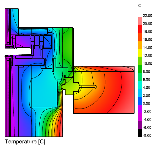
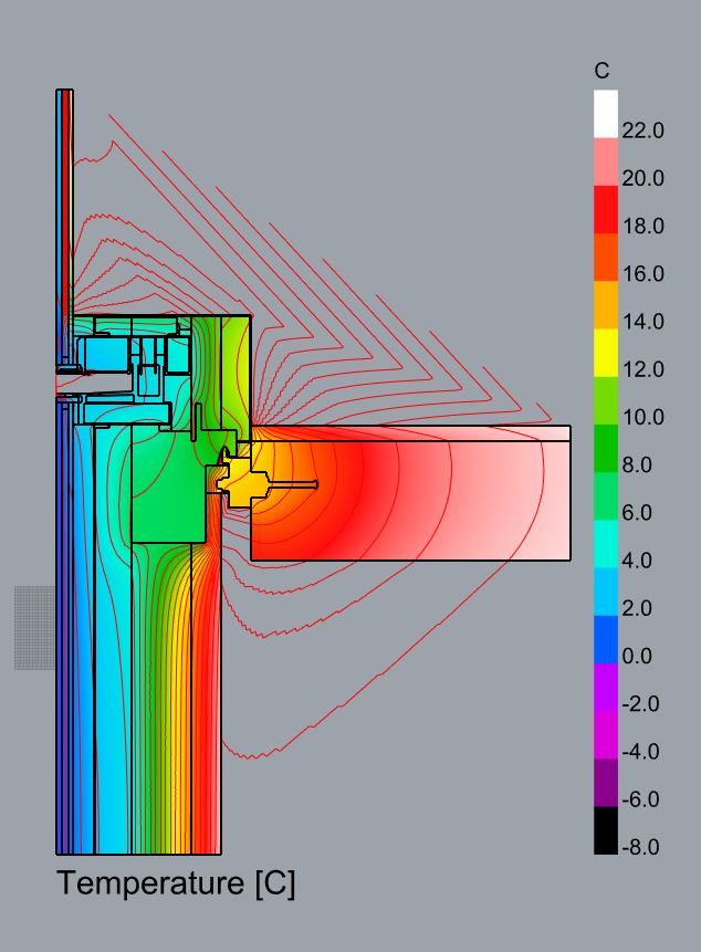
Ah, thank you for testing everything with such a big construction detail, @remyweather . This is quite possibly one of the largest I have seen for this level of detail.
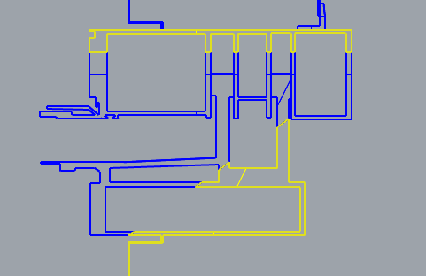
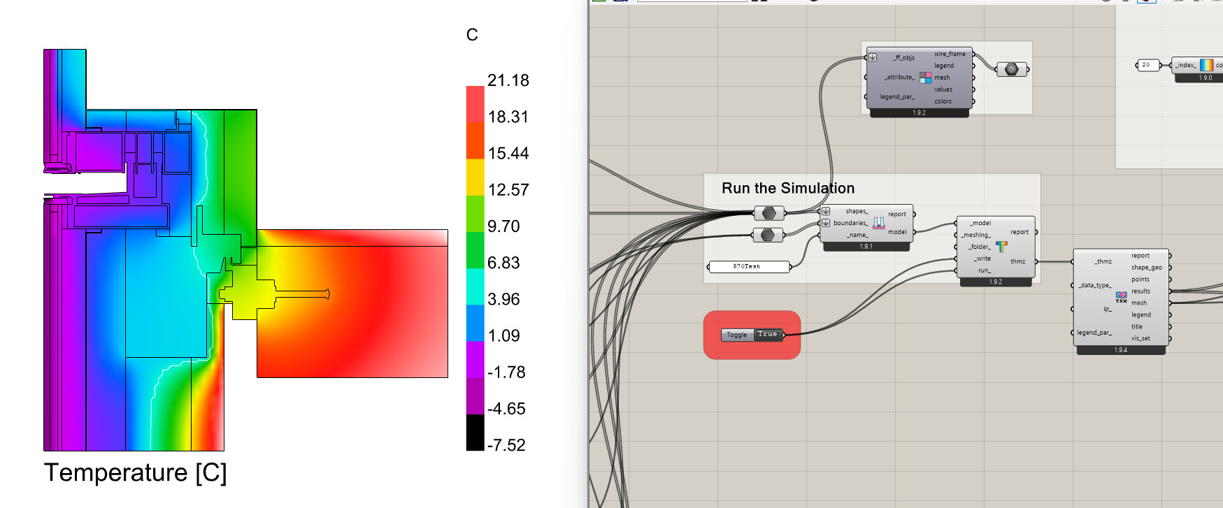
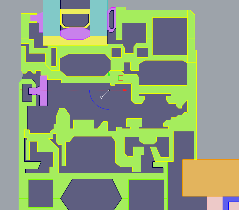
You can be pretty confident whenever you have this situation:
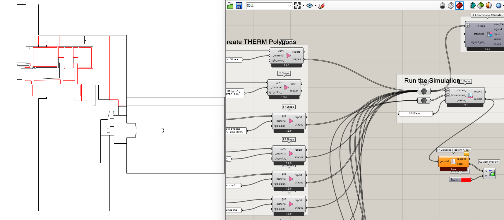
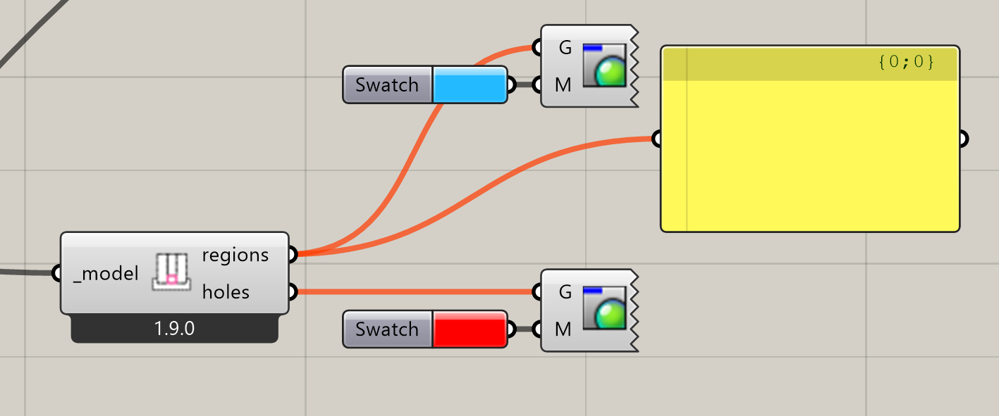
… it is a bug. I’ll look into it more but I assume that the model you have uploaded here is already split. I see some of the holes have been manually split while others have not. If you get the chance to upload the model that recreates this error, I’d appreciate it.
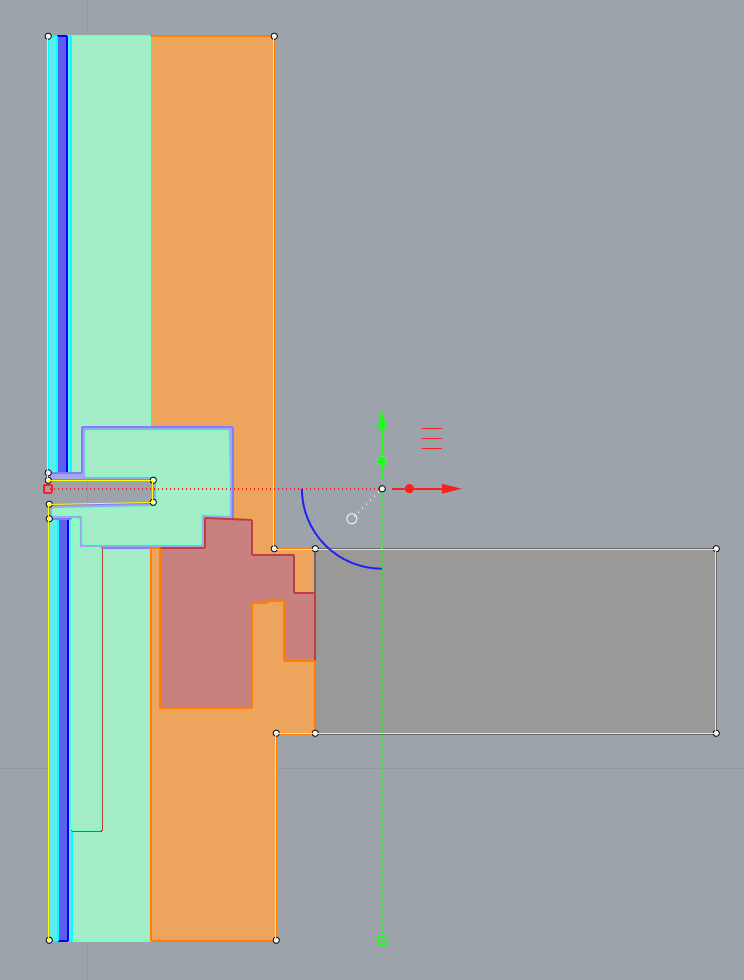
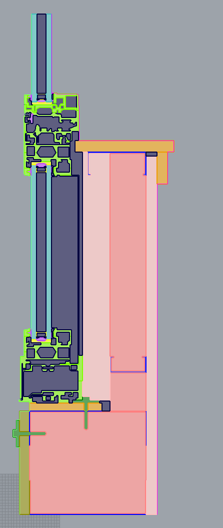
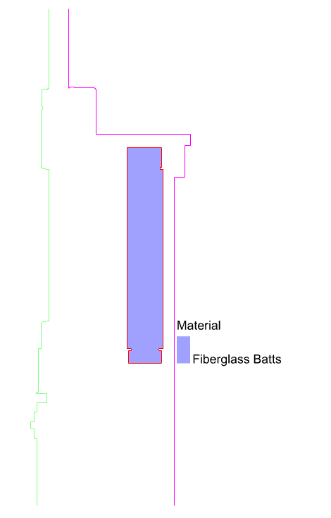
Now to get to the blocker. For the life of me, I cannot figure out why THERM is failing here. When I open the model in THERM, there is nothing highlighted in red. The geometry with ID 115 that it is complaining about is this one:
I checked the THMZ and the coordinate values for this shape are clean in the 2D THERM canvas:
326.2, -377.8
329.0, -377.8
329.0, -342.7
268.5, -342.7
268.5, -694.8
276.0, -694.8
276.0, -697.8
271.5, -697.8
271.5, -720.4
329.0, -720.4
329.0, -697.8
324.7, -697.8
324.7, -694.8
332.0, -694.8
332.0, -380.8
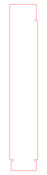
326.2, -380.8
… making a neatly-closed polygon:
I notice that, even when I change the order of the shapes, it always complains about shape with ID 115. So it seems like it always highlights the 115th polygon in the file as problematic.
Now I am wondering if there is some implicit limitation in THERM that it just does not permit you to simulate a model with more than 115 shapes. Let me do a few more tests and see.