Hole Found, but no hole found - Simple CW - Modelling practices?

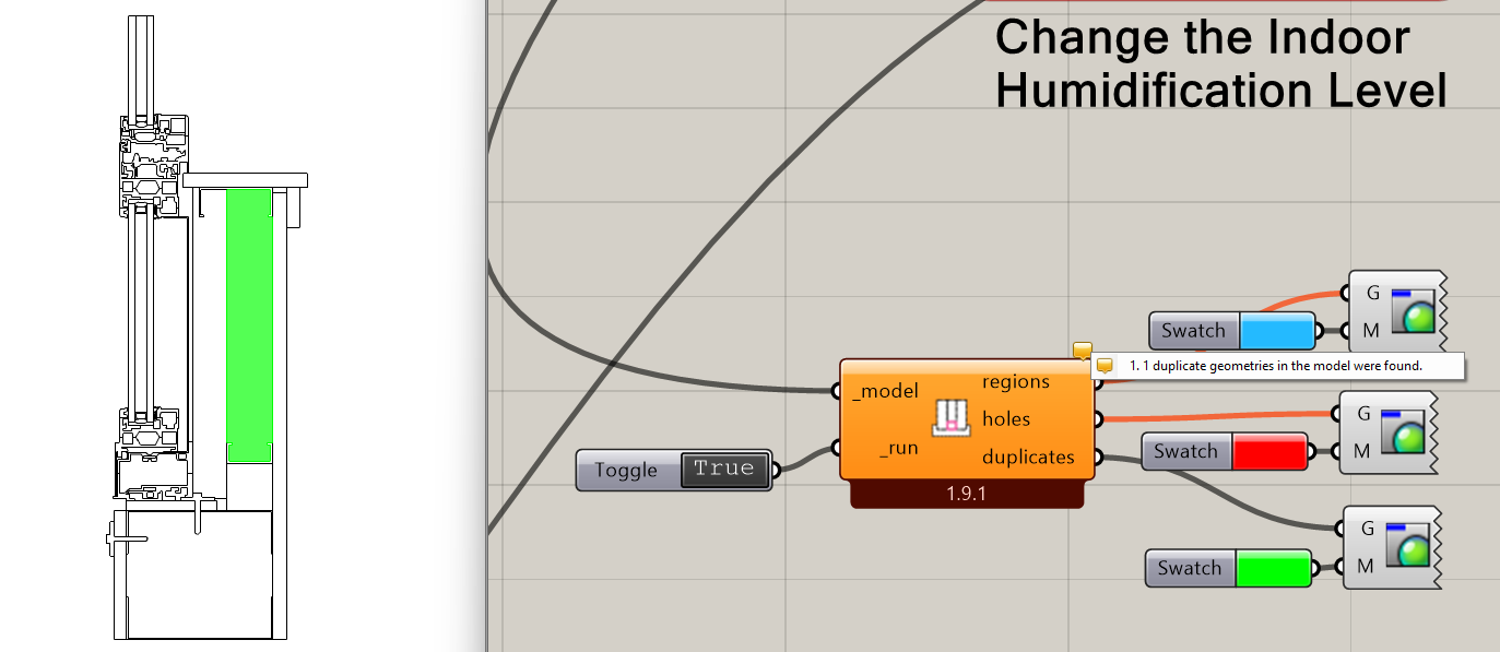
Ahh, I found the problem, @remyweather . It seems that you assigned the same geometry there to be both Urethane/Polyurethane:

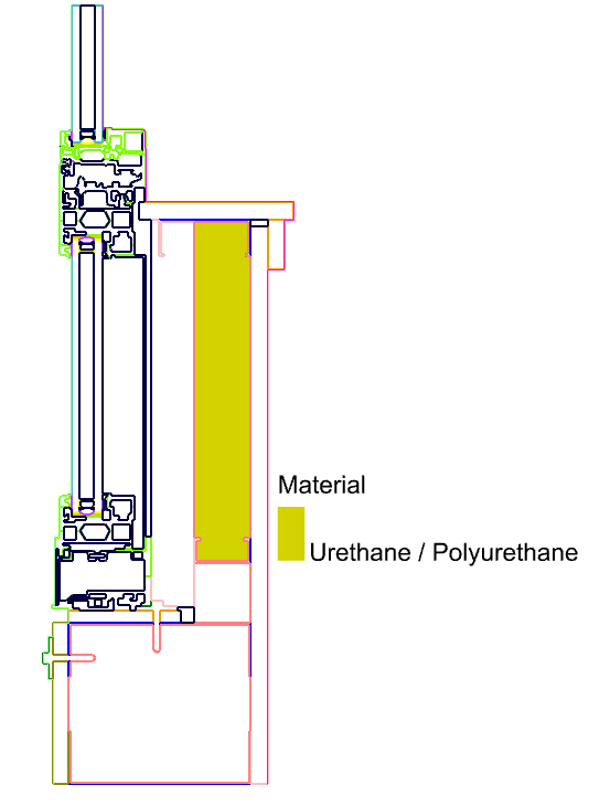
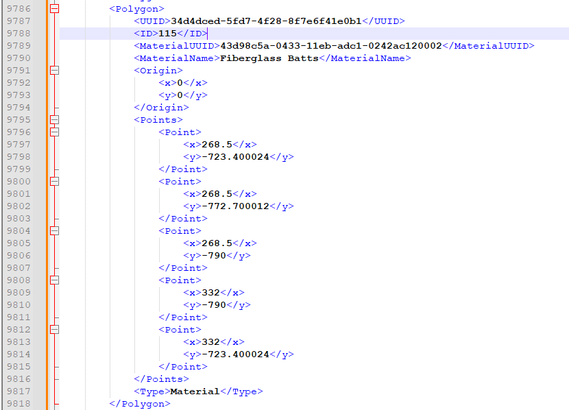
… and Fiberglass Batts:

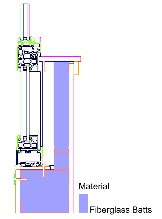
The 115 ID was for the Urethane Shape, which is why I did not notice any change as I changed the order of the Fiberglass shape. So definitely just an error in our model setup and not a fundamental limitation of THERM.

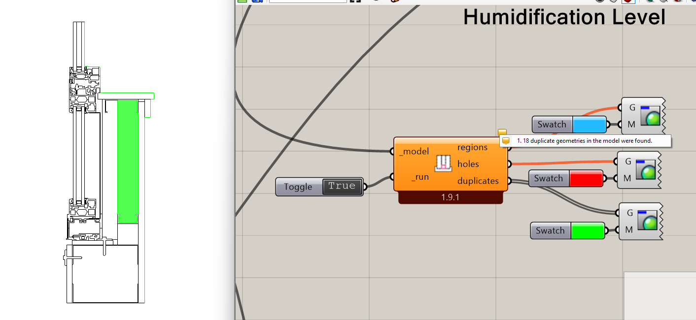
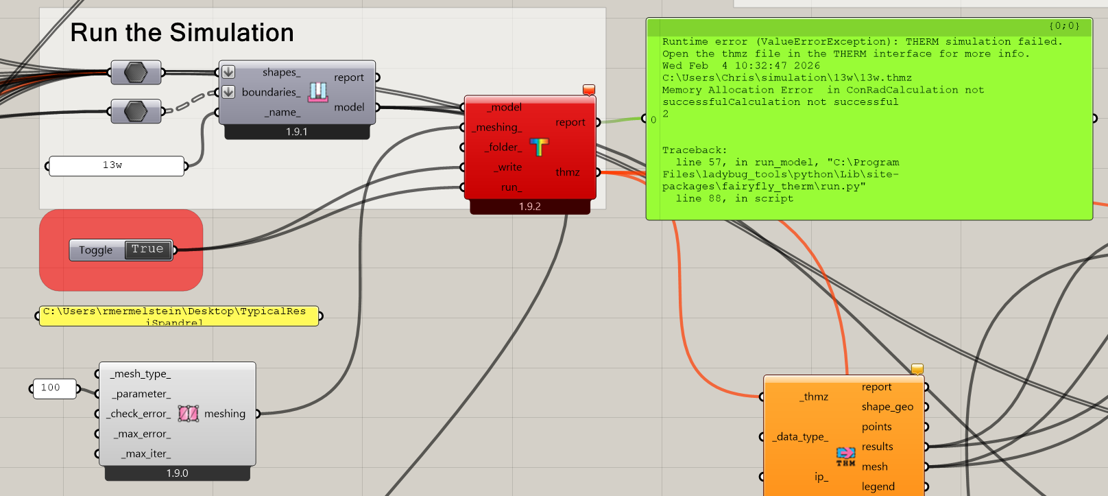
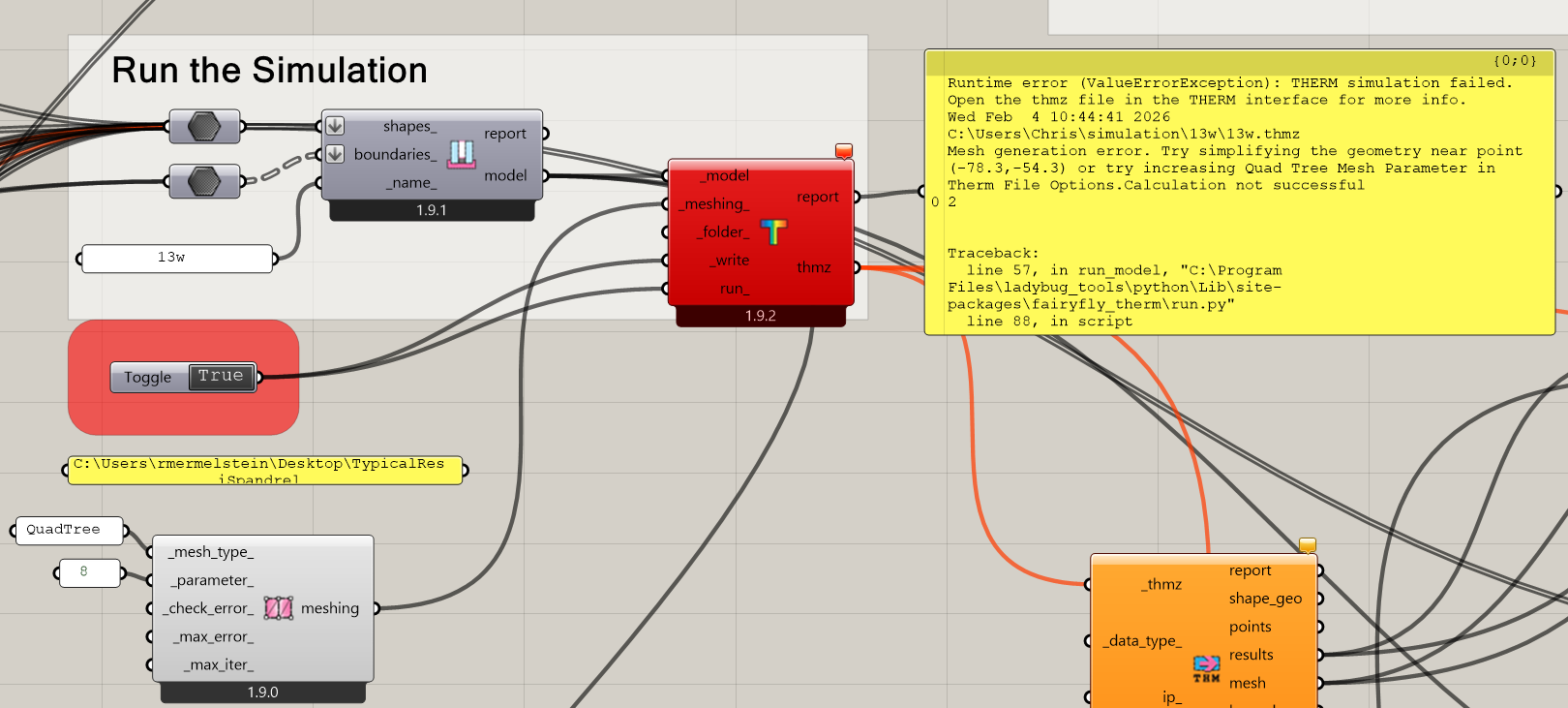
Once I remove the geometry from the Urethane and I set the mesh parameter to something a bit smaller, everything simulates well:

Here is the .gh file where I have gotten everything to work:
TypicalResiSpandrelTHERMTest.gh (168.7 KB)

So I’m inclined to say that the only definitive bug here is the error about holes that you experienced before manually splitting the shapes (and I would still greatly appreciate a file that recreates the issue).

And, while the duplicate shape issue isn’t technically a bug in Fairyfly, it seems like we would all benefit from me implementing a better check for this case of duplicated geometry somewhere in the process.

If I can do it during the translation to THMZ and give a clear error about the duplicated shape that you need to check, this could be nice. But I’d only consider this if I can implement it in a way that it did not significantly increase the runtime of the “FF Model to THMZ” component. Right now, most of the ways that I can think of are a little computationally heavy.

Instead, maybe I can add a new output to the “FF Visualize Problem Areas” component that reports any duplicate shapes or boundaries. And, given that this altogether is going to make this component’s runtime a little longer, maybe we add a boolean toggle _run input to give better control over when the check runs.

I guess the last option would be to implement a validation routine for Fairyfly models similar to the one we have for Honeybee. But this could be a lot of work and the messages that it would give are probably not as immediately helpful as a visualization of the duplicated geometry.

So I am leaning towards adding a new input to the “FF Visualize Problem Areas” component right now. Let me know if you feel otherwise or if you have any other thoughts about this.

3 Likes

Ahh, I feel quite dumb right now! I re-assigned geometry so many times to the BREP container, I’m not sure how that happened. Let me try it again. thank you @chris

A check for (dumbos) like me would be nice for sure, but I understand if it is not a priority.

I guess what would be helpful - how can you tell what the 115 ID shape is? I was trying to figure that out but did not know where quite to look, is that just looking at the list of shapes out of the model output and going to the 115th one and highlighting that?

This is useful to know you can see the coordinates, I am assuming you just opened the THMZ in notepad or something to see that? Like looking at an energy plus error file.
Well, I am glad my testing has revealed my own weaknesses since I am learning, and some minor bugs in the product, thanks again chris. We on the team here are extremely excited about this and how we will apply it to our projects.

Let me try again to replicate it on my own!

Is there a reason you set the mesh parameter smaller, other than to save time? Higher mesh parameter = higher resolution, correct? The default of 20 (?) correlates to what approximately? or just what you guys found works best?

If I may jump in on this, I suggested the value of 20 based on a few trials with the first THERM test I made (Fairyfly user feedback), looking for a balance between high-ish mesh density and short-ish simulation time.

The issue was that a lower setting was messing with the final mesh color display when there was a high temperature jump between two points: my example showed the mesh jumping from black to green while skipping the purples and blues due to a lack of intermediate points. If I remember correctly the previous mesh parameter was set to 5 or 10. I went up to 50 on the same test, but the simulation was taking a few seconds too long for an unnoticeable change in mesh quality.

I also noticed that smaller shapes get a much higher density of points than larger ones, so probably a lower setting might be ok with details containing a lot of small shapes, like your example above. At the end of the day what matters is a perceived acceptable simulation time, I guess.

@remyweather ,

Definitely no need to feel dumb. You might have been the first user to report this type of problem for the new Fairyfly plugin but you almost certainly will not be the last. If I had to guess, some of those “Legacy THERM issues” that you searched the forum for might have been cases of duplicate geometries for which we did not have good debugging tools at the time. Plus, if it took me a while to figure out what was wrong, then this is clearly something subtle for which we could use some better tools to help troubleshoot.

I just pushed an update to the “FF Visualize Problem Areas” component:

Now, it reports the duplicated geometries in the model and I verified that it does so correctly for your original .gh file:

… and it also reports duplicate boundary geometries in the event that these are accidentally double-selected:

So this should hopefully help us all diagnose these issues before they cause issues in the THERM interface.

As the above change indicates, my goal is to give us good enough troubleshooting/validation tools such that you never need to go digging around in the .thmz file. However, I can answer this:

I would just ask that, if you find yourself having to dig around in the .thmz file to debug stuff, please let me know about it here on the forum so that I can think of changes to make the components to make it easier to debug.

The .thmz file is essentially just a .zip file with its file extension changed. So, if you manually change the extension of the .thmz file to .zip, you can unzip it using any standard decompression tool. Inside, you will find a bunch of .xml files that make up the file and there are separate ones for materials, boundary conditions, the mesh, and the results:

It is the Model.xml that contains all of the geometry in the 2D THERM canvas and it has each polygon along with it’s integer ID:


You may want to “Pretty Print” the XML using something like Notepad++'s XMLTool to make the XML human-readable. Again, if you find yourself having to do this (or even if you find yourself debugging things in the THERM interface instead of Grasshopper), let me know and we can come up with a better way to debug things in Grasshopper.

As @Gspahr indicated, this one is more of an art than a science but there are some limitations that prompted me to lower the mesh parameter from the 100 that you had in the original file you uploaded here. Because your model has such a high complexity of detail, @remyweather , a mesh parameter as high as 100 was causing the finite-element solving routine to run out of memory:

So you definitely want to use something lower when you have a complex model like this. If all that you cared about was accurate U-Factors, you can use a pretty coarse mesh parameter (something like 8). The THERM error estimator does a pretty good job adding more mesh subdivisions where they are needed to ensure accurate U-values. But you will probably find that the result mesh in this case is not as smooth or good-looking, which is why @Gspahr and I settled on 20 as a default value. It reliably gives good-looking results while not taking that long to run and with a nearly non-existent risk of running out of memory.

However, this does bring up a question that I have, @remyweather - would you mind if I shared your spandrel detail here with the team at LBNL or if I used it in promoting the fairyfly plugin? As I said earlier, this is probably the most complex THERM model that I have seen to date and I can see that it is a model that never would have run in THERM 7 because its QuadTree mesher cannot handle this level of complexity:

So it’s a really good example for showing off the new capabilities that the Fairyfly plugin has over Legacy. And I’m sure that the level of complexity in this model would serve as a good test case for the THERM team at LBNL. I totally understand if you would rather I not do this but, if you are ok with us using it, I will be sure to credit you as the modeler wherever I use it. Just let me know.

@chris thanks again for everything.

Just updated via versioner and tested the new visualize problem areas, works like a charm.

Absolutely

ahhh ok, I was wondering how everybody was seeing this extra detail! thx!

Understood re the meshing, thanks @Gspahr too

Go ahead and share!

1 Like