I would need to create a metal perforated radiance material for a glare analysis using the LBT.
I saw this script (Hydra Viewer), which explains how to create it with the legacy version, but I don´t find for the new LBT1.3 the component Honeybee_Add to Radiance Library, I can’t find it, or is it not yet available?
Possibly, would there be another method?
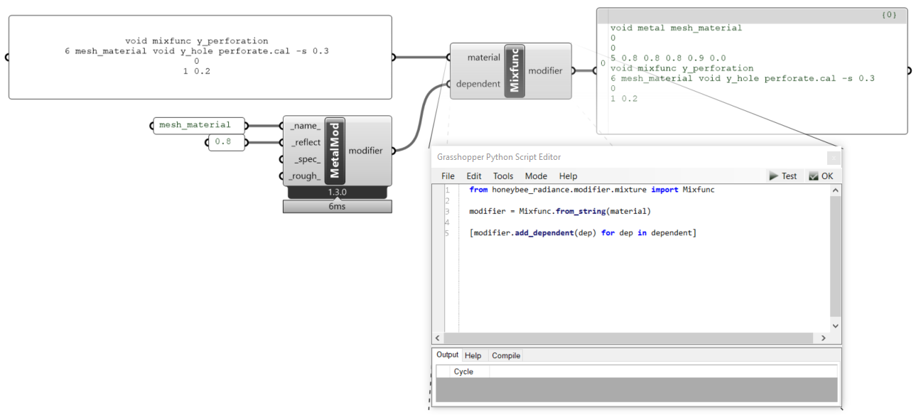
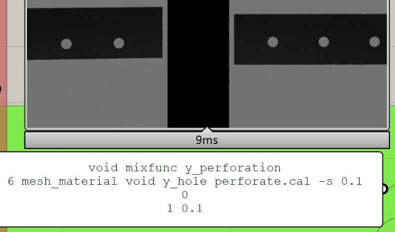
To recreate that example, you can use the Mixfunc class. In the example below I use the from_string method. We can add mesh_material using the add_dependent method. As you can see in the right panel, this method will add the modifier before the mixfunc modifier. If you want to replace void* with a modifier, you can simply add another modifier to the input dependent - as you can see in Python it adds all modifiers in the list called dependent.
*I mean this “void”: “6 mesh_material void y_hole …”
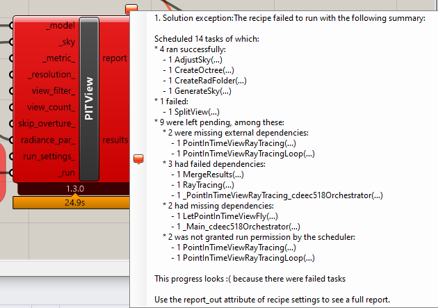
I tried to test the perforated material inside the LBT sample file for the ViewBased solution and the PitView component give me this error:
did I do something wrong?
Hallo dera Mikkel,
sorry if I bother you, I hope you can resolve a my doubt.
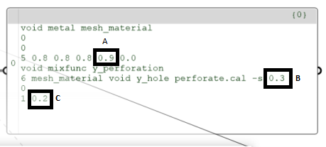
I don´t understand how to manage the dimensions and the distance between the perforation.
What do the values A, B and C in the 3 strings?
I thought the B and C values controlled the size of the perforation, but I don’t understand with what criterion.
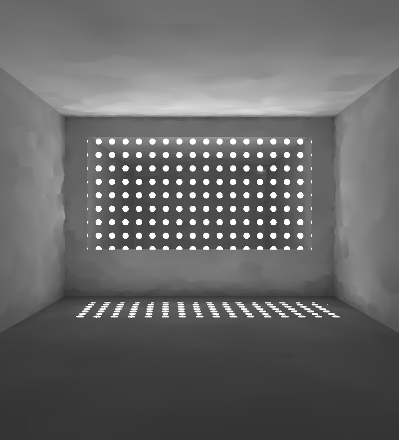
Per ex. in the screen below, the height of the blind is 10cm, but when I set 0.1 (is this 10cm?) in the string, the diameter is much smaller.
The value A is the specularity of the metal Radiance modifier. Dion Moult got some examples of different values. The default in LBT is what you got - 0.9.
The value B is used to scale the perforation (it is 1 by default). C is the relative size of the circles (the radius). In perforate.cal this value is referred to as A1, so I will name it like that in the following.
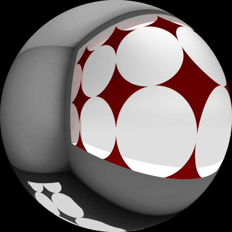
In this example the surface has the following dimensions: width: 5.0 m, height: 2.5 m.
Settings: -s 1, A1 0.5
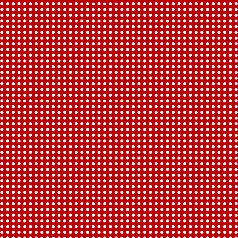
As you can see, since the relative radius is 0.5 m, I get 2.5 circles along the height.
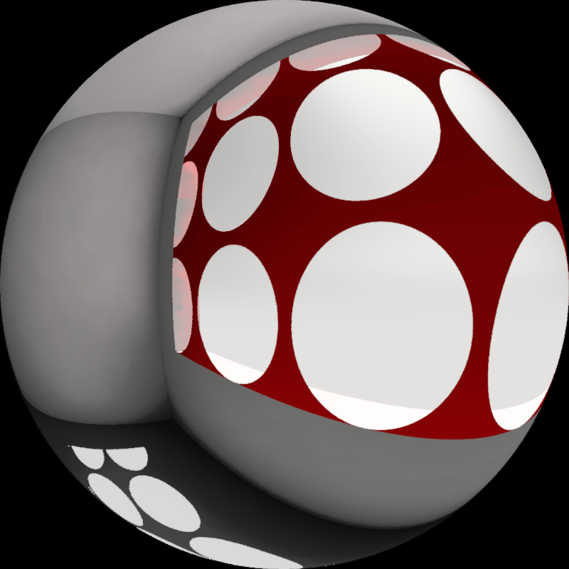
Settings: -s 0.01, A1 0.45
Further scaling of 0.01. Now the radius is 0.45 cm. Diameter is 0.90 cm. If I wanted the holes to have a diameter of 1.00 cm (radius = 0.005 m) I would have to scale by 0.005 / 0.45 = 0.0111… instead of 0.01.
In your image you have set the radius to 0.1 m and then scaled by 0.1, so the radius is 0.01 m. This means the circle diameter is 2 cm, which judging by your image seems a reasonable estimate. Try start with -s 0.01, A1 0.5 (after scaling: radius 0.5 cm, diameter 1.0 cm). Check if this gives a result like my first image where the circles are just touching each other.
thank you for your thorough explanation,
I needed a 1,1mm (diameter) perforation with a 2,4mm between the holes (is this distance editable?).
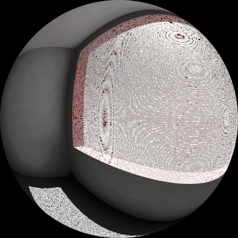
This i the result, do you think the perforation is so small that it cannot be properly visualized or am I wrong in the calculation?
I don’t think you can edit the distance. You will have to control the distance by the circle diameter - as the diameter decreases the distance increases - and then scale afterwards. If the 2.4 mm is the distance between the centre of each circle here is my best guess on how to get that with a diameter of 1.1 mm:
We need to find the radius. We can use the ratio 0.55 / 2.4. r = 0.55 / 2.4 = 0.229167.
Now that we have the radius we can scale the perforation. You want the radius to be 0.00055 m. Use the formula I mentioned above: 0.00055 / 0.229167 ≈ 0.0024.
Try: -s 0.0024, A1 0.229167.
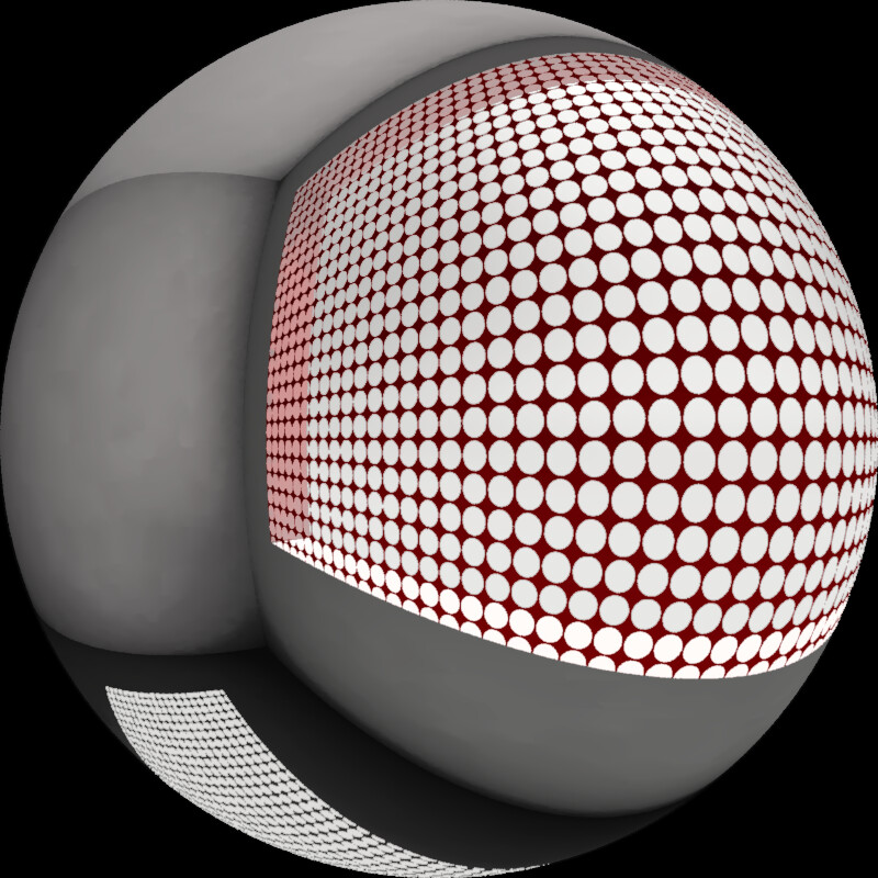
This image shows a 100 mm x 100 mm surface with the above settings. The view point is rather close to the surface so the perforation is clearly visible. I think with a small size like 1.1 mm you don’t have to move far from the surface to get to a point where it cannot be properly visualised.
unfortunately I need to disturb you again for a last help.
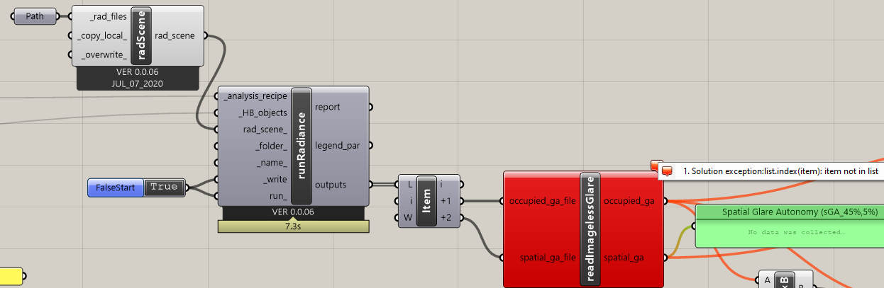
To have the same metal perforated material in HB+ (to test and work with your imageless DGP script) change the procedure in writing the python file? How can add it into the + version?
Go to scene/extra in the written folder. Likely to be “C:\ladybug\untitled\gridbased_imagelessglare\scene\extra” if you didn’t add any input to _folder_.
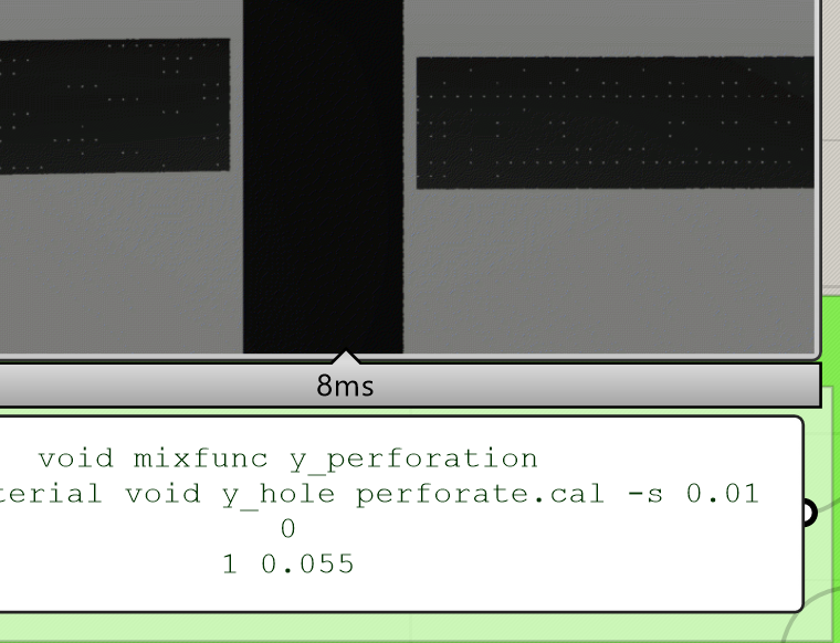
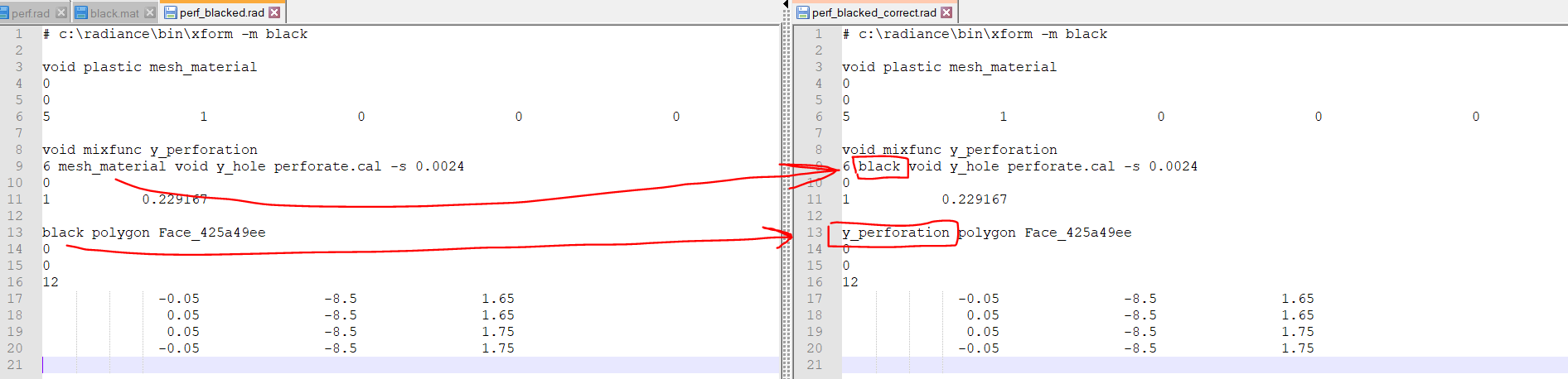
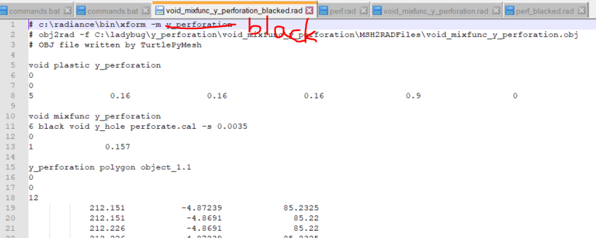
Edit the file blacked scene file you added to the recipe. Mine is called “perf_blacked.rad”. The needed changes are seen in the image above.
Go to “C:\ladybug\untitled\gridbased_imagelessglare” and run the batch file called “commands.bat”. If you try to run the recipe in runRadiance component it will re-write and the edited file will be gone.
I edit the new blacked.rad files into the “C:\ladybug\untitled\gridbased_imagelessglare\scene\extra”, following your screen (are the strings written correctly?)
Seems correct. As long as you edit the generated file called [insert_filename]_blacked.rad (and overwrite the file with your changes).
Sorry, I see I didn’t make it perfectly clear that you should NOT run “runRadiance”. So the process goes:
Write “runRadiance”.
Edit [insert_filename]_blacked.rad.
Run “commands.bat” manually by double-clicking the file.
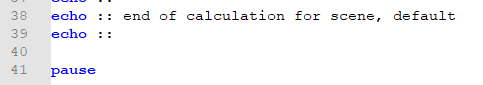
3.1. Optionally, add “pause” at the end of “commands.bat”. This will let the cmd window stay open after executing the Radiance commands so you can see if Radiance reports any errors.
Import the result files in Grasshopper manually instead of using the output of “runRadiance”.
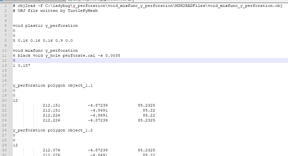
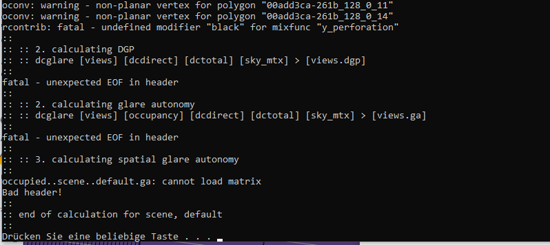
I really don’t know why black.mat is not there when writing the files.
Furthermore, the first line of void_mixfunc_y_perforation_blacked.rad is wrong. See below. I am also not sure why this is incorrect if this is how the file was written by the recipe. But you can make these changes manually and then run commands.bat manually.
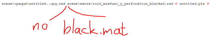
EDIT: Nevermind about the last thing I mentioned. I think it should run if you just add scene\extra\black.mat as shown in the first image.