Making openings in Honeybee with(out) ArchiCAD

Hello there! Another tutorial coming up for those using ArchiCAD. But I guess it also might be helpful for those working only in Grasshopper and Rhino or with any other design application. Today I’ll try to share with you my way of dealing with openings :slight_smile:

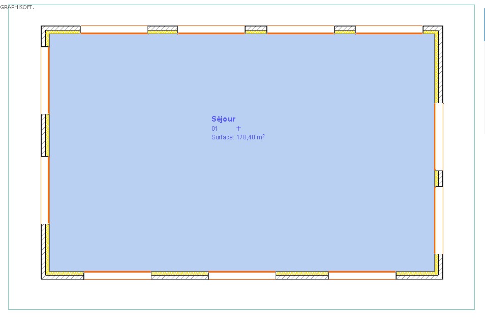
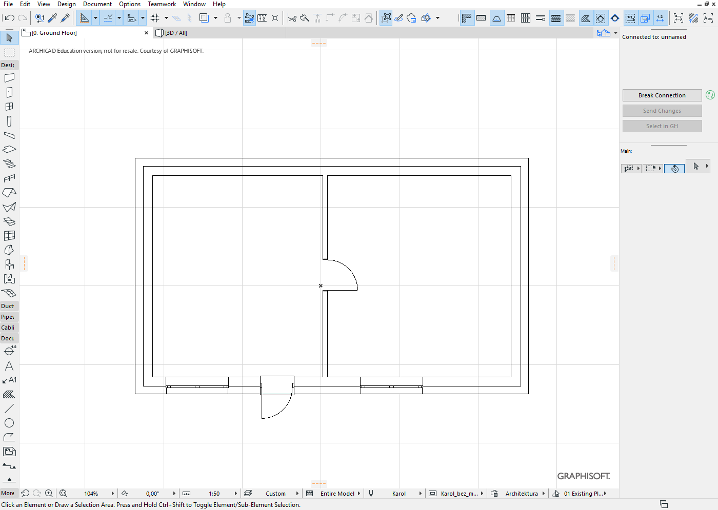
We’ll start with making simple plan, 4 exterior wall and 1 interior. Additionally 2 windows and 2 door as shown below.

This is our model in 3D window.

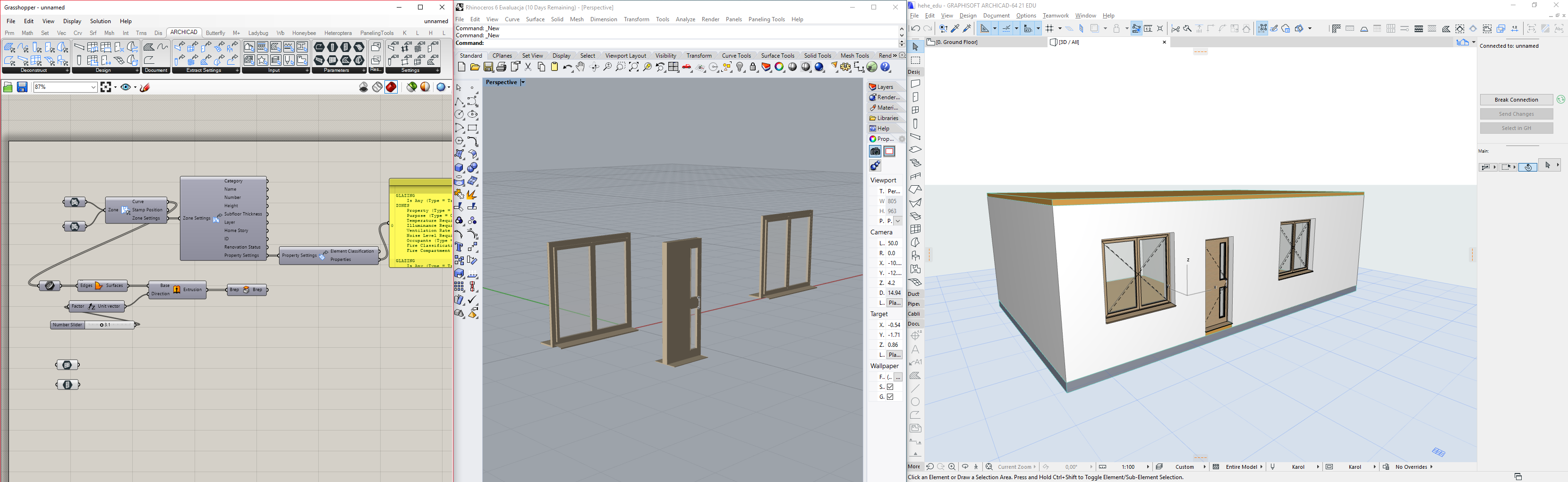
In the next step will connect our ArchiCAD with Grasshopper. Whole process including installation is covered in previous tutorial. :slight_smile: Also in that step I exploded our ArchiCAD elements to get some informations about them. Next thing was creating simple breps out of them.

WINDOWS

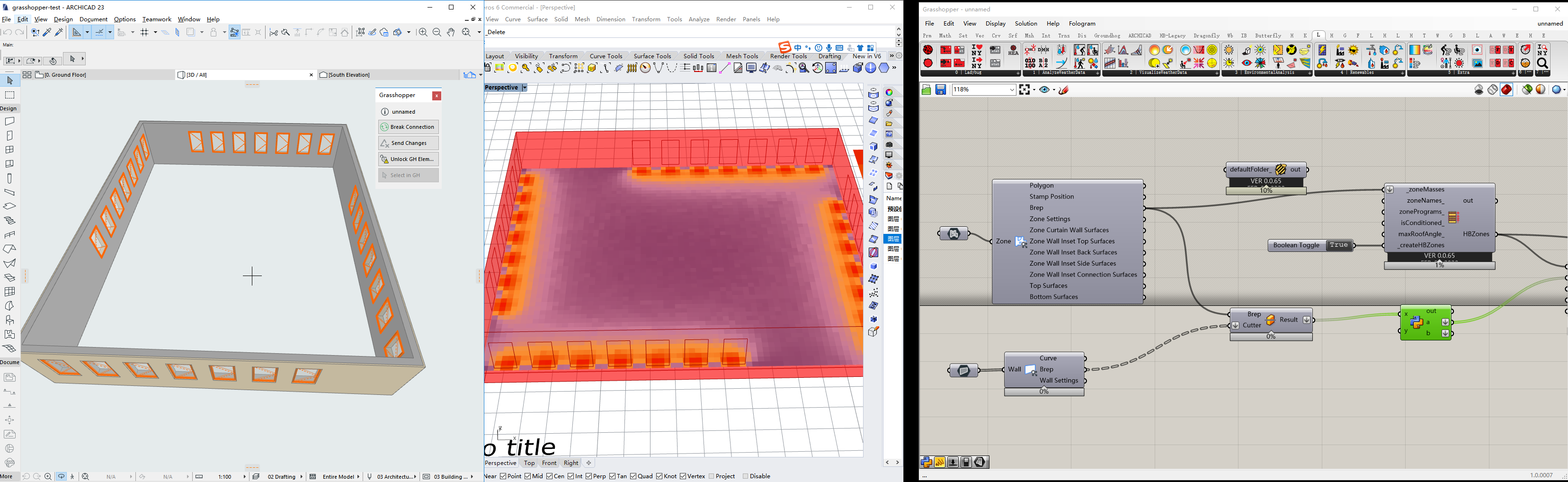
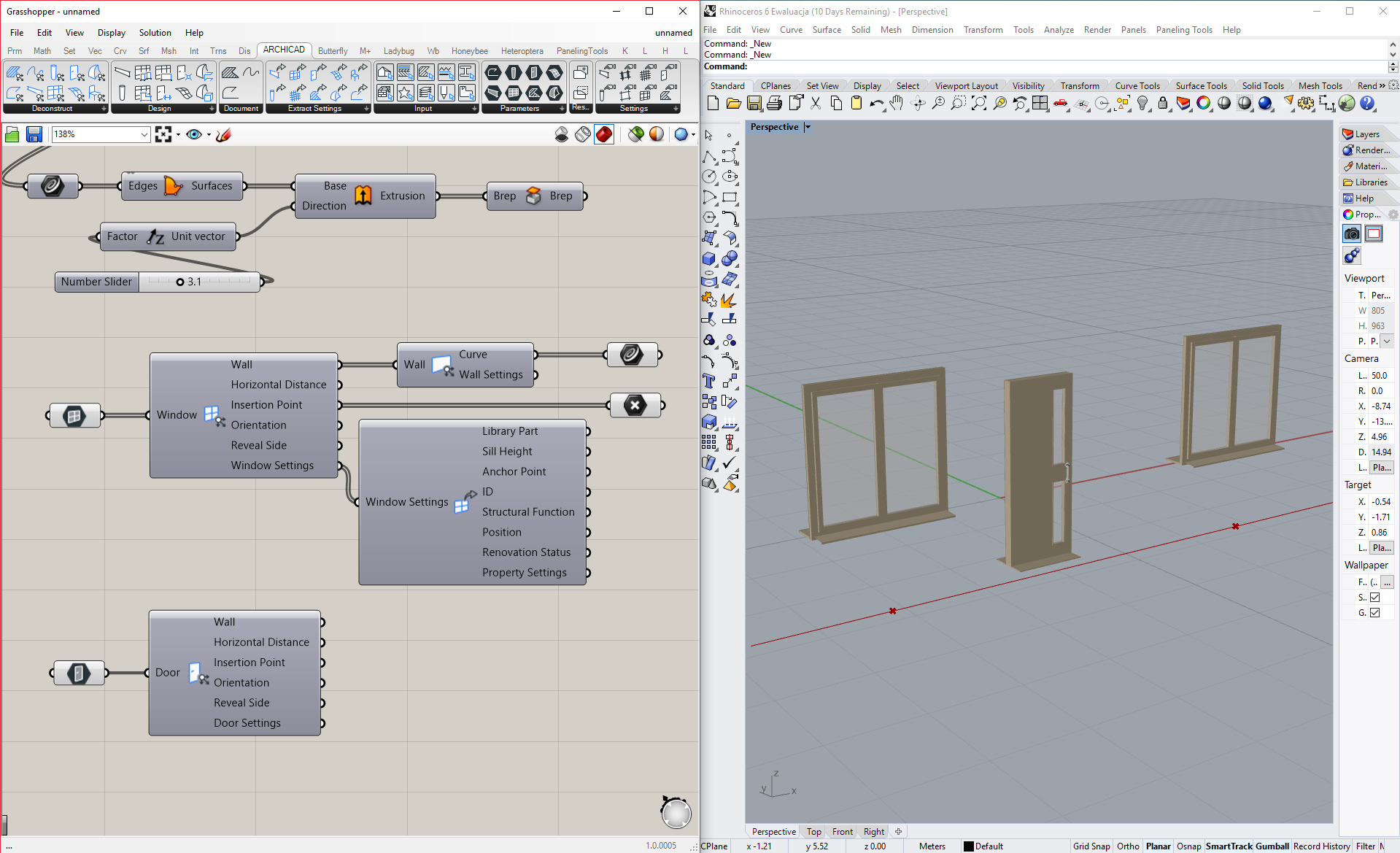
Now we’re gonna do very similar thing to what we’ve done before with zones. So we grab [Windows] block from parameters, select it, now select our two windows in ArchiCAD and finally click with RMB on [Windows] and select “Select multiple windows in ARCHICAD”. These objects should now be clearly visible in Rhino as shown below.
(I already did the doors as well.)

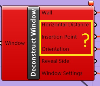
Now the sad part. Sadly, Live connection doesn’t offer to much in terms of exploding openings geometry so this process won’t be as much parametric as I would like. Hopefully I’ll change soon. :slight_smile:

So, to overcome this obstacle I just do it manually. At least some of it. Knowing the dimmensions of my opening, I just draw rectangle in Rhino with exacly the same dimmensions and match them with imported models.

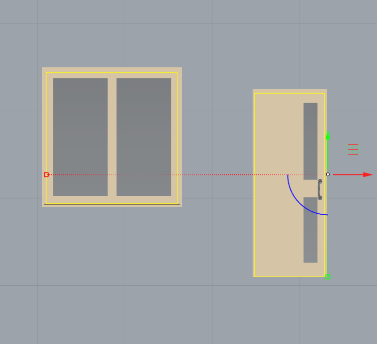
After this, next step is to get out rectangles outside our brep.

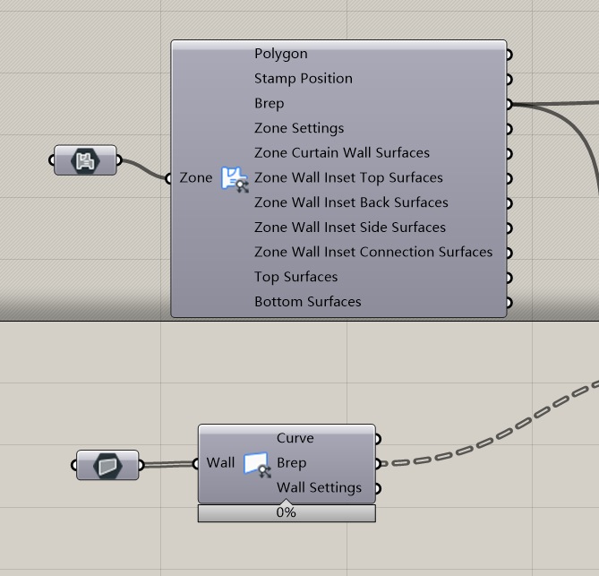
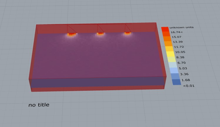
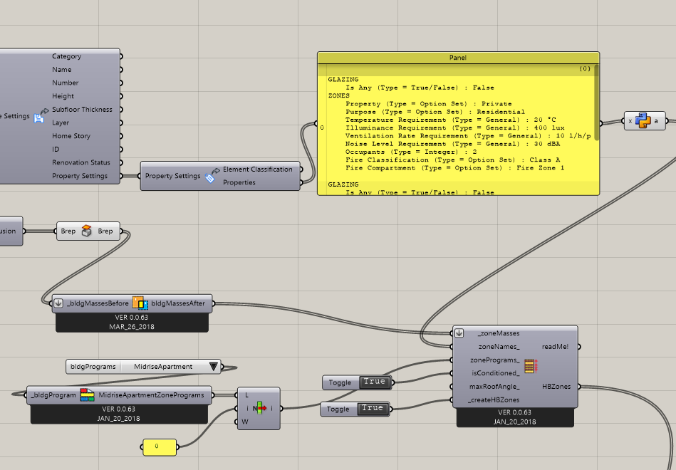
Now we will focus more on our zones, soon to be HBZones. At this moment I’m making simple connections to make HBAdjacencies work.

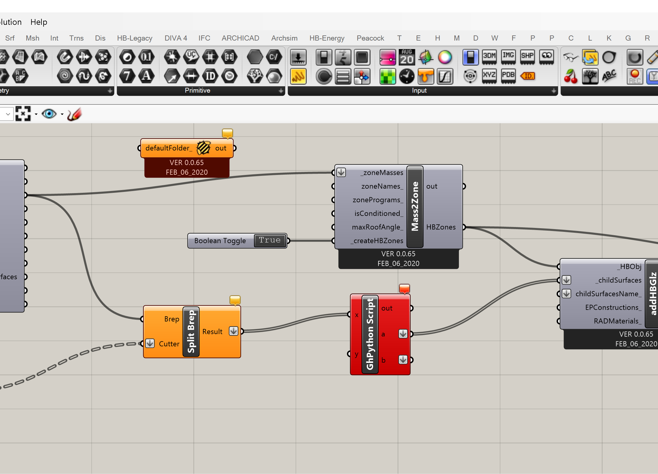
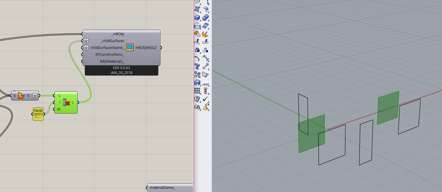
What happens next is the key part. We’re gonna split our HBZones into separate blocks, and then use [Project], which is native Grasshopper component, to project our windows rectangles, which me made earlier, onto our zones. Making it this way we’re always 100% absolutly and positively sure our windows and walls are on the same plane. Always.


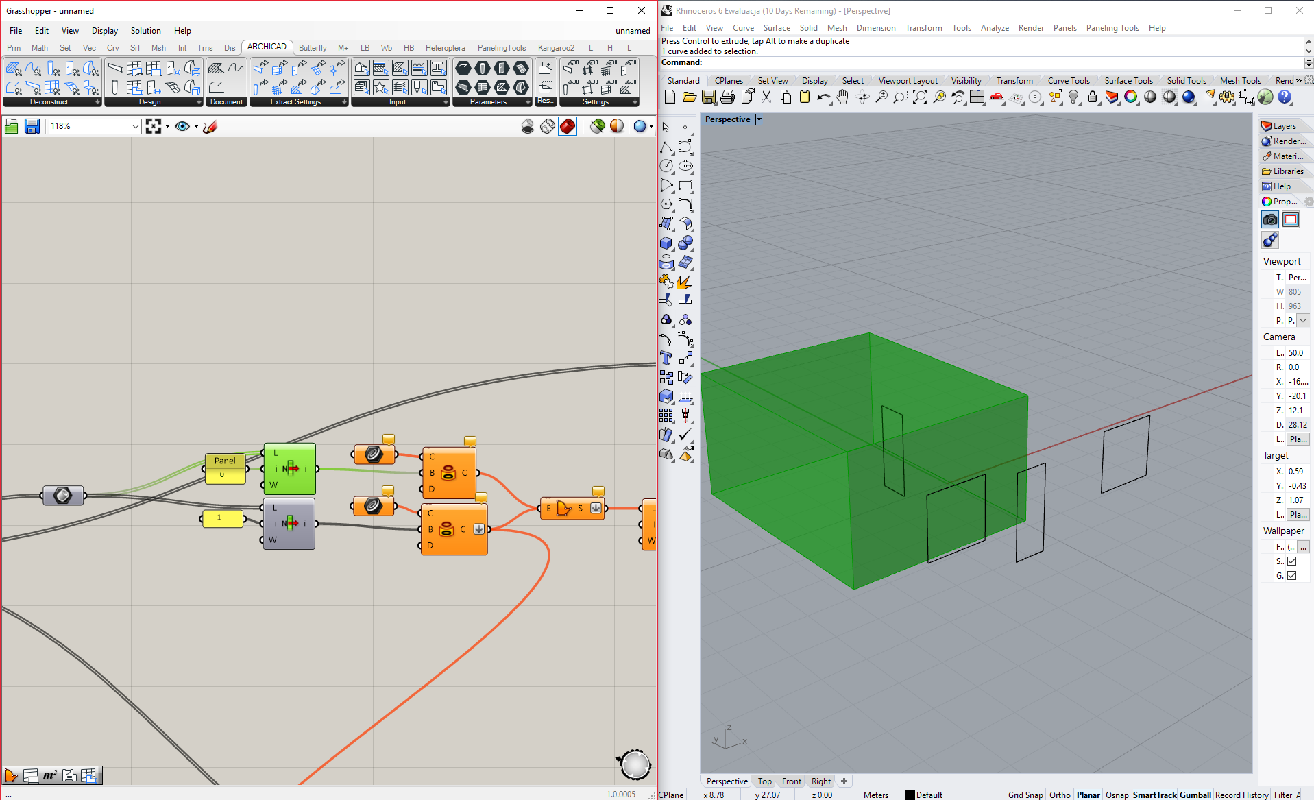
Then you should see, that your windows are projected on both side of the zone. That’s when the [Cull index] component comes helpful. We’ll just cut out unnecessary windows. Now we’re ready to connect it to our [HBObjWGLZ].

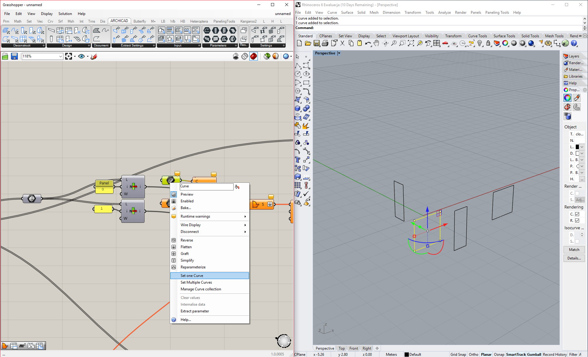
But what if we want to make some shading? It’s very easy. Just take your projected curve.

DOORS

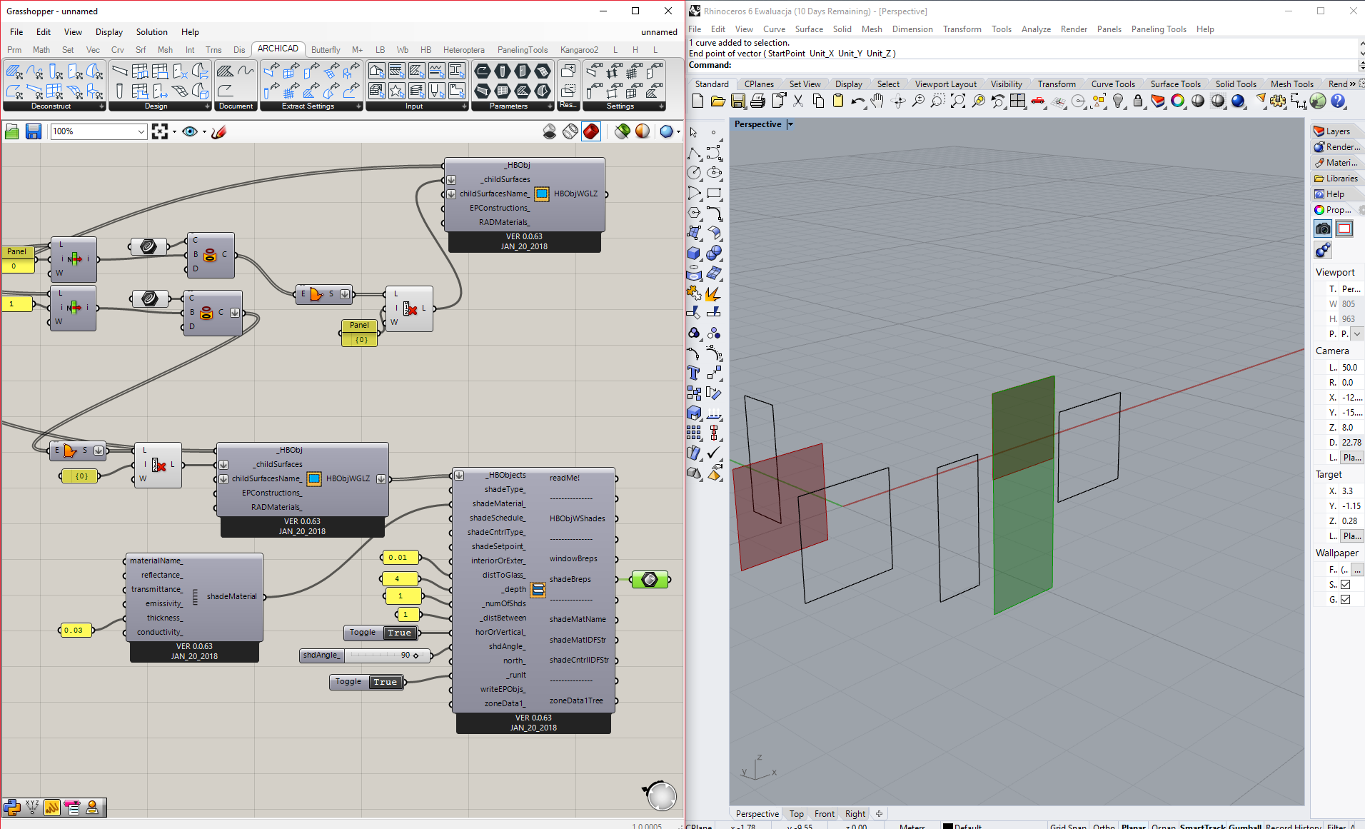
Workflow with doors is really similar to windows. We take our simple zone, explode it to surfaces, then select the one that we’re interesed in and simply cut out the door shape.

At this point we’re left with two surfaces - wall and door, which in most cases would be completly enough but for now let’s go even further! Let’s say that I want to have more control and be able to open those at desired angle.

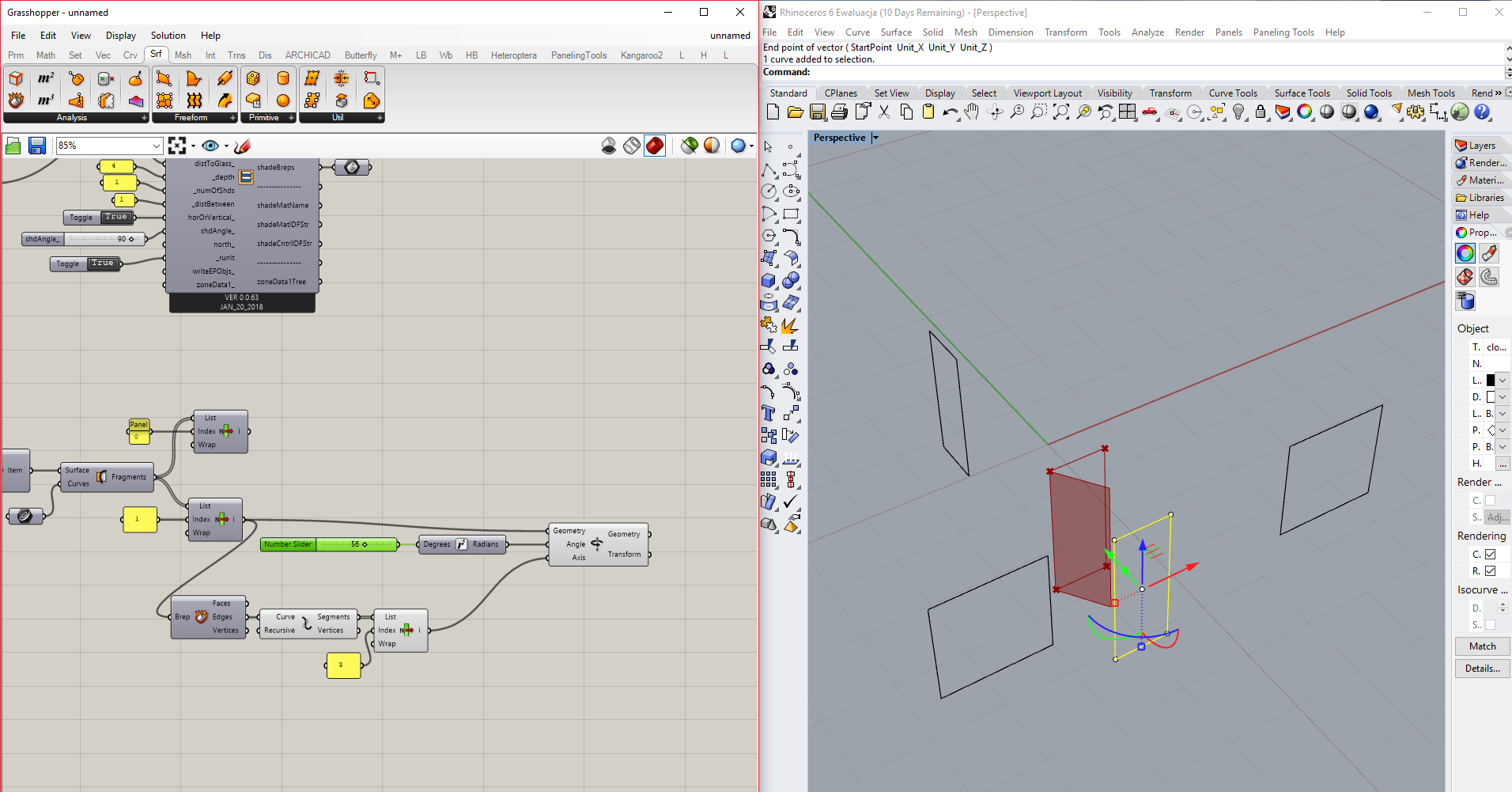
To do this, we simply take out doors surface, explode it to edges, take the one which would be the axis and simply rotate it. Volie!

Probably with a little bit more time it would be possible to make it work with schedules to!

Workflow with interior doors would be pretty much the same as with the exterior. The only difference, very, veery important though is that you have to project your doors from both side of the wall, and when you’ll be done cutting then out, remeber that one of the surfaces will be your doors while another one HAS TO BE MADE AIRWALL. Thats all I guess. Have fun guys! :wink:

3 Likes

@Avik Thanks for your sharing. But in my experience,your method is too complicated. I recommend exporting gbXML with ArchiCAD and importing Honeybee. The method I mentioned is quite simple and efficient.

Hi Avik,

Thanks for sharing this tutorial, the information is interesting.

However, after trying your tutorial, I’ve realized that window frames are not imported, do you have any idea of how to deal with?

And how do you deal with different building floors? Do you create one zone that represent the whole building like a “building body”?

Best regards,

Frank

What do you mean by “not imported”? Is it a problem with live connection (yellow / red component) or the frames are not visible? And with floor I’d say it is a matter of how detail do you want it to be. But in most simple way I just do zones on different floors and import them to grasshopper where the rest is happening. And no, I do not create one zone, it would be too big simplification and could lead to misleading output. You should create a zone where one exists. :slight_smile: It doesn’t mean every room or something similar. You’ve got to decide where different conditions appear and decide where to create next zone. But yeah, in a simple house I’d say that there would be a different zone in almost every other room. :slight_smile:

Hi Avik,

Actually, the window frames from ArchiCAD are imported but with the method you explained we should also draw manually the window frames. I couldn’t find yet a way to automatically import the window from ArchiCAD as they were. It’s not so efficient to draw all the windows manually especially when you have a bigger building with a lot of windows. Is there any way that we could extract the Surface from ArchiCAD not only the curve?

Regarding the floor, I agree, it depends of how details you want to do your calculation. But just a small question regarding the way you create your zone. You are taking the zone from ArchiCAD with the internal and external wall, then your honeybee find the internal and external wall but how do you do when you have different kind of internal walls for instance?

Moreover, for Daylight simulation, how do you add internal wall inside your zone, do you create new internal wall into grasshopper?

Thanks in advance for your answer, I hope my questions are clear.

Best regards,

Frank

So, with the first thing. It’s one of those things in LiveCon that can make sad. It’s… not that easy. But possible. I’ve made an example file for you. It’s easy and logical at one hand but at the other… Such simple thing should be made by very simple method, rather not like this. I’d call this a work-around. At least that’s what came to my mind in the first place. Maybe there’s a better way, but… I don’t know about one. The definition is made for an AC window 1,5 x 0,9 m. The rest should be self-explanatory but if you have any questions feel free to ask.

That would be for LiveCon but you can always export gbXML as @minggangyin mentioned above. I haven’t tried it myself yet but it could be worth your attention. :slight_smile:

For the second thing, the one with the walls, I could say that we’re stuck almost in the same spot. The only option for this is to “explode” your zone into single surfaces in HB, set them with new materials and then combine them back into new zone. That way you can (and kinda have to) describe every surface in your zone from scratch. In my case problem is with what’s after. I started to have many issues with zones created that way (tilted surfaces for example), but it’s not always the case so I’d say - give it a try. :slight_smile:

The last question is not clear enough for me and I don’t want to sound stupid or to say some useless things. Of course adding another wall can be made using every software on the way so ArchiCAD, Rhino and Grasshopper. Question is what do you need. Because if it’s only purpose is to create shade then I’d recommend playing with shading context or similar options. Specify your question and surerly we’ll find something out. :slight_smile:window.gh (71.0 KB)

Hi Avik,

Thanks for your complete answer and for the grasshopper file you made for me. I’ll give it a try and come back to you. I was actually thinking of exporting the geometry as DWG from ArchiCAD and import it in Rhino. It won’t be a “live Connection” but at least it could be faster to get the geometry. I’ll come back to you if i’ve found an easy way to import with DWG to Rhino.

Regarding the gbXML, in ArchiCAD there is no native gbXML export function so you need to install something else and not sure how the result from gbXML will be. So later I could give it a try, but there are many other wy Before this one :slight_smile:

Yes, it’s seems a long process in case of different wall, so actually it’s faster to assume all internal wall to be the same.

And for the last question it was about the Daylight simulation. When you perform Daylight simulation you need to know the reflectance of the internal surfaces (Wall, floor, ceiling, etc…). So in some cases, you have internal wall in the middle of the zone you have created so I was thinking if it could be possible to add those wall within Grasshopper directly with an automatic process. But I don’t think so it’s to create them into Rhino manually.

So for energy simulation it could be possible but then, we can’t use this process for Daylight simulation.

Hi Frank!
Sorry that you’ve had to wait so long for reply. With gbXML there are issues but not where you are looking. There is a native way of exporting gbXML from ArchiCAD, and it exist since ArchiCAD 20. Just go to Energy Evaluation under the Design tab. Next to "Start Energy Simulation there’s a little arrow. After you’ve done with AC simulation you can easly export gbXML. Problem is that this file is worth absolutlety nothing - at least in my case.
Yes, with internal walls assuming that all of them are the same is definietly fastest way and I’d say still pretty accurate.
With Daylight simulation it seems that you know what’s going on so I’ll leave you at that. :wink: Good luck with your project! And come back if you’ll have any questions - I’ll whatever I can. And of course tell us when you’ll find something on yourself! For now that’s the only way for us to learn those tools. :wink:

Hi Avik,

I’m still doing some research with GH-ACH regarding openings and other stuff. As soon as I have something interesting I’ll post it here. Thanks for the information regading the gbXML, I’ll take a look at that later.

I have one question that you may be able to answer. In the script you sent me, in order to get the window from ArchiCAD, you are using a component to deconstruct the window which is great but I am wondering what are the horizontal distance and the orientation means? What values in ArchiCAD corresponds to those parameters? Maybe we could extract information such as height of window and width maybe?

Here you can see a screenshot of what I am talking about.
Deconstruct%20window

Have a nice day,

Frank

Those values are sadly almost useless. Orientation coresponds to little sun that appears in AC while putting a window in a wall. So it tells you which way is “outside” for the window. You have to define it if you create a window in Grasshopper using AC components and it’s defined as a point.
Horizontal distance is a distance measured from wall starting point to window insertion point - also kinda useless.
And insertion point is a point at which a window is placed in a wall. I belive I used it in my definition (I can’t check it, I’m on my phone right now). Hope this clears some things out. :slight_smile:

All right, so there is not much to expect from those values then.

I might have found another way to insert a window and convert for Grasshopper. You can select 3 points in ArchiCAD in order to create a rectangle in Grasshopper and that correspond to your opening. But still, we lose the live connection. You have to select again the 3pts to get the new window if any change. So it’s another way but still not the best.

Well it sounds pretty close to what I sent you - 3-point rectangle. Although I’d say that once set it is more or less live. Once you move such window it should do the same in Grasshopper. And it wouldn’t be that hard to deal with greater amount of such openings in AC.
Still, it’s far from perfect. Same goes for zones. Once you import it using Zone component you see “brep”, 3D version of such zone. Yet it is impossible to use that box. You have to manually make it using zone polygon and other GH components. Just as weird and counter intuitive as it could get.
The only thing thats left in those situation is a hope that live con won’t be forgotten to soon by Graphisoft.

@Avik I have created a simple workflow for generated opening in Grasshooper.

  1. import zone and wall from ArchiCAD.
  2. use brep of wall to split the brep of zone.
    3.We will get some open brep and trimed surface. The trimed surface is the geometry of the windows. I use ghpython to extract it.

Blockquote
“”“Provides a scripting component.
Inputs:
x: The x script variable
y: The y script variable
Output:
a: The a output variable”“”
“”"
author = “21223”
version = “2020.08.04”

import rhinoscriptsyntax as rs
a =
b =
if rs.IsSurface(x) is True:
a.append(x)
else:
b.append(x)
“”"

  1. Use mass2zone to generate the thermal zone.
  2. Use Addglaz compotent to generate the windows.
    Finally I do a daylight analysis for this example.
2 Likes

Hi @minggangyin. Can you please share your script.

@Asisnath Here is the demo file.
ac-gh.gh (491.2 KB)

Thank you @minggangyin. So this workflow can be used with energy simulation too!!!

Hey! It looks absolutely stunning and finally useful! I wasn’t using the tools for a little while now but I see that they certainly developed a lot. That’s cool that they offer so much more than a year or two ago and that they are still updated. Thank you for your method - much more straight forward, elastic and finally - can be fully parametric! I am definitely gonna give it a go!

Hello
Merci minggangyin for this job.
I am wondered too about shading objects from Archicad to Grasshopper.

Hi again,
Goot some warnings and error.
I’m Working on Archicad 23 French.